Virtex-6 FPGA System Monitor
27
UG370 (v1.1) June 14, 2010
System Monitor Control Logic
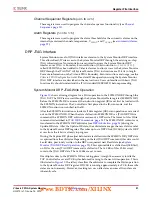
ADC Channel Averaging (
4Ah
and
4Bh
)
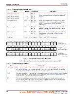
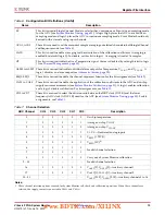
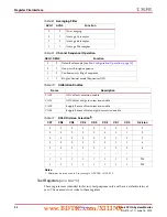
The ADC channel averaging registers enable and disable the averaging of the channel data
in the sequence. The result of a measurement on an averaged channel is generated by using
16, 64, or 256 samples. The amount of averaging is selected by using the AVG1 and AVG0
bits in Configuration register 0 (see
). Not all
channels in the automatic sequence have an averaging feature. The bit definitions for these
registers are described in
and
. Each bit in the two 16-bit registers is used
to enable or disable the averaging for its associated channel. A logic 1 enables averaging
for a particular channel in the sequence. All channels have the same amount of averaging
applied as defined by AVG1 and AVG0 (see
).
Averaging can be independently selected for each channel in the sequence. When
averaging is enabled for some of the channels of the sequence, the EOS will only be pulsed
after the sequence has completed the amount of averaging selected by using AVG1 and
AVG0. If a channel in the sequence does not have averaging enabled, its status register will
be updated for every pass through the sequencer. When a channel has averaging enabled,
its status register is only updated after the averaging is complete. An example sequence is
Temperature and V
AUX
[1] and averaging of 16 is enabled on V
AUX
[1]. The sequence will be
Temperature, V
AUX
[1], Temperature, V
AUX
[1], ... Temperature, V
AUX
[1] for each of the
conversions where the temperature status register is updated. The V
AUX
[1] status register
is updated after the averaging of the 16 conversions.
If averaging is enabled for the calibration channel (by setting CAVG logic Low), the
coefficients will be updated after the first pass through the sequence. Subsequent updates
to coefficient registers will require 16 conversions before the coefficients are updated.
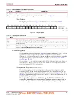
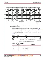
12
4
20
VAUXP[4],VAUXN[4]—Auxiliary channel 5
13
5
21
VAUXP[5],VAUXN[5]—Auxiliary channel 6
14
6
22
VAUXP[6],VAUXN[6]—Auxiliary channel 7
15
7
23
VAUXP[7],VAUXN[7]—Auxiliary channel 8
16
8
24
VAUXP[8],VAUXN[8]—Auxiliary channel 9
17
9
25
VAUXP[9],VAUXN[9]—Auxiliary channel 10
18
10
26
VAUXP[10],VAUXN[10]—Auxiliary channel 11
19
11
27
VAUXP[11],VAUXN[11]—Auxiliary channel 12
20
12
28
VAUXP[12],VAUXN[12]—Auxiliary channel 13
21
13
29
VAUXP[13],VAUXN[13]—Auxiliary channel 14
22
14
30
VAUXP[14],VAUXN[14]—Auxiliary channel 15
23
15
31
VAUXP[15],VAUXN[15]—Auxiliary channel 16
Table 14:
Sequencer ADC Channel Selection, Control Register
49h
(Cont’d)
Sequence
Number
Bit
ADC
Channel
Description
www.BDTIC.com/XILINX


