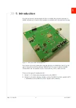
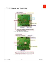
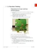
background image

AirPrime XA12xx and XM1210

Development Kit User Guide

41112817

Rev 1.2

Summary of Contents for AirPrime XM1210

Page 1: ...AirPrime XA12xx and XM1210 Development Kit User Guide 41112817 Rev 1 2 ...

Page 2: ...ircraft the Sierra Wireless modem MUST BE POWERED OFF When operating the Sierra Wireless modem can transmit signals that could interfere with various onboard systems Note Some airlines may permit the use of cellular phones while the aircraft is on the ground and the door is open Sierra Wireless modems may be used at this time The driver or operator of any vehicle should not operate the Sierra Wire...

Page 3: ...ered trademarks of Microsoft Corporation Macintosh and Mac OS X are registered trademarks of Apple Inc registered in the U S and other countries QUALCOMM is a registered trademark of QUALCOMM Incorporated Used under license Other trademarks are the property of their respective owners Contact Information Revision History Sales information and technical support including warranty and returns Web sie...

Page 4: ...1 Preparation for Power and Data Communication 11 Application for RF Reception 13 Software Usage 14 System Requirements 14 USB Driver and GNSS Tool 14 Installing the USB Driver 14 Using GNSS Tool 16 Allystar USB Driver 18 Sensor Device Driver 20 Troubleshooting 22 Setup Troubleshooting 22 Causes of Poor GPS Signals 23 ...

Page 5: ...Kit 12 Figure 3 4 External Active Antenna Attachments 13 Figure 3 5 Patch Antenna Module 13 Figure 4 1 Driver Installation Folder 14 Figure 4 2 Starting the Installation Process 15 Figure 4 3 Selecting Manage 15 Figure 4 4 Accessing the Port Properties 16 Figure 4 5 Main Program Screen 17 Figure 4 6 COM Port Dialog 17 Figure 4 7 Allystar USB Driver Installation Folder 18 Figure 4 8 Start the Allys...

Page 6: ...Rev 1 2 Nov 18 6 41112817 List of Tables Table 5 1 Troubleshooting Causes and Solutions 22 Table 5 2 Examples where Poor GPS Signals may Occur 23 ...

Page 7: ...his device can communicate with computer devices via USB cable and it must be used in conjunction with the software GNSS Tool for users to record all GNSS module data such as satellites status time to first fix TTFF date and time There are two types of development kit 1 Series 1 is for stand alone modules such as the XM1210 2 Series 2 is for patch antenna modules such as the XA1210 which supports ...

Page 8: ...Development Kit User Guide Rev 1 2 Nov 18 8 41112817 Figure 1 2 Series 1 Development Kit Board Figure 1 3 Series 2 Development Kit Board ...

Page 9: ... properly again once it receives clear GNSS signals works normally under the open sky Select a suitable external active antenna based on the satellite system that you use Packing Contents The development kit is delivered with USB cable External active antenna You will also need the following documents and software which are available on the Source User manual Software Application Program CP210X US...

Page 10: ...Rev 1 2 Nov 18 10 41112817 2 2 Hardware Overview Figure 2 1 Series 1 for XM1210 Parts and Features Figure 2 2 Series 2 for XA1210 and XA1220 Parts and Features ...

Page 11: ...tus 1PPS LED Indicator is blinking with a green light 3D fix status Figure 3 1 Power is On and Module is Ready for Data Connection 3 Push button SW2 to power reset the development kit 4 Push button SW3 SW4 to wake the module up from sleep mode 5 Use the Boot ROM to upgrade firmware on the GNSS module Refer to the following steps a Push SW1 SW5 until the module is powered on b Connect the USB cable...

Page 12: ...Development Kit User Guide Rev 1 2 Nov 18 12 41112817 Figure 3 2 Button Position on Series 1 for the XM1210 Development Kit Figure 3 3 Button Position on Series 2 XA1210 and XA1220 Development Kit ...

Page 13: ... Reception 1 External active antenna with a GNSS module on the Series 1 for XM1210 Development Kit Figure 3 4 External Active Antenna Attachments 2 Built in patch antenna module on the Series 2 for XA1210 and XA1220 Development Kit Figure 3 5 Patch Antenna Module ...

Page 14: ...S Tool Before setting up the connection between the module s UART port and the PC you will need the Development Kit USB Driver CP210x VCP and GNSS Tool exe to operate the Development Kit Please download and install the USB Driver CP210x VCP from https source sierrawireless com resources airprime software cp210x windows drivers Please download the GNSS tool from https source sierrawireless com reso...

Page 15: ...ting the Installation Process 3 After the installation is complete you may need to restart your computer Please follow the instructions on screen to restart your computer 4 After the computer restarted right click on My Computer and select Manage Figure 4 3 Selecting Manage ...

Page 16: ...l COM port number generated for the USB connection to the Development Kit This generated COM port value must match the COM port value in the program setting for the application to establish proper communication with the Development Kit After completing the installation please proceed to Using GNSS Tool Using GNSS Tool Microsoft Framework 4 5 or higher is required before you launch the GNSS Tool so...

Page 17: ...his menu item will display the CNR signal window 4 Sky View clicking on this menu item will display a window with a sky view of satellites 5 Statistics Plot clicking on this menu item will display the statistics plot window 6 Map clicking on this menu item will display the map window After the Development Kit is connected with the PC please choose the correct COM Port and Baud Rate then click the ...

Page 18: ...te the Development Kit Please download and install the USB Driver Allystar GNSS USB from the Source Important Please check whether you have the correct USB driver before you proceed to the next step The Development Kit will not function without the correct driver To install 1 Go to the driver installation folder and double click ALLYSTAR_GNSS_USB_Driver exe to begin driver installation Figure 4 7 ...

Page 19: ...rt your computer 4 After your computer has been restarted right click on My Computer and select Manage Figure 4 9 Select Manage 5 Left click Device Manager and select Universal Serial Bus controllers Check to see if a device named ALLYSTAR GNSS is present If so the Devel opment Kit is set up and ready for use Figure 4 10 Accessing the USB Port Properties ...

Page 20: ...ule s USB port and the PC you will need the Allystar Sensor Location Driver to operate the Development Kit Please download and install the GNSS Sensor device driver from the Source Important Please check whether you have the correct USB driver before you proceed to the next step The Development Kit will not function without the correct driver To install 1 Go to the driver installation folder and r...

Page 21: ...t your computer 4 After your computer has been restarted right click on My Computer and select Manage Figure 4 13 Select Manage 5 Left click Device Manager and select Sensors Check to see if a device named DriverCoding Location Sensor Device DEMO is present If so the Development Kit is set up and ready for use Figure 4 14 Sensor Device Driver is Installed ...

Page 22: ...ously No NMEA data or GNSS signals 1 USB was not set up properly 2 COM Port or Baud rate value is incorrect 1 Check to see if the USB connector to the PC or Development Kit is connected properly 2 Double check to see if the proper COM Port and Baud rate value are selected Poor GNSS Signal Reception 1 If it is used inside a vehicle the anti sunscreen film on the windshield may interfere and weaken ...

Page 23: ...ible to have weak GNSS signal in the following situations Table 5 2 Examples where Poor GPS Signals may Occur Inside a tunnel where the GNSS signal is blocked Underneath infrastructure e g a bridge where the GNSS signal is blocked Inside a building where the GNSS signal is blocked ...

Page 24: ... and may result in no GPS reception GPS satellites are property of United States Army Sometimes they will tune down the accuracy for unknown reasons In such cases the GPS position may not be accurate Next to tall buildings where the GNSS signal is weakened Underneath forests or any other kinds of canopy where the GNSS signal is weakened Table 5 2 Examples where Poor GPS Signals may Occur Continued...

Reviews: