Chapter 6 – Parameters
6-34
ACH 500 Programming Manual
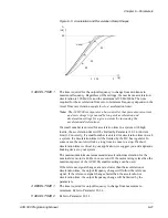
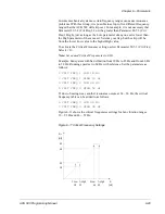
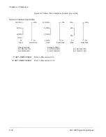
Figure 6-13 shows motor thermal time.
Figure 6-13 Motor Thermal Time
5 MOTOR LOAD CURVE
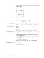
The Motor Load Curve sets the maximum allowable operating load of the
motor. The load is adjustable from 50% to 150%. Refer to Figure 6-12 for an
example of motor load curve.
When set to 100%, the maximum allowable load is equal to the value of Start-
up Data Parameter F (Motor Current -FLA).
6 ZERO SPEED LOAD
This parameter defines the maximum allowable current at zero speed to
define the Motor Load Curve. Refer to Figure 6-12 for an illustration of the
Motor Load Curve.
The current is adjustable from 40% to the Motor Load Curve set by Parameter
30.1.5 (Motor Load Curve).
7 BREAK POINT
This parameter defines the point at which the motor load curve begins to
decrease from the maximum value set by Parameter 30.1.5 (Motor Load
Curve) to the Zero Speed Load (Parameter 30.1.6). The value is adjustable
from 1 Hz to 500 Hz. Refer to Figure 6-12 for an example of motor load
curve.
8 STALL FUNCTION
This parameter defines the operation (
NO/WARNING/FAULT
) of the Stall
Protection. The protection is activated if:
•
The motor current exceeds the limit set in Parameter 30.1.9 (Stall Current),
•
The output frequency is below the level set in Parameter 30.1.10 (Stall
Time/Freq), and
Motor
Load
100%
Temp.
Rise
63%
Motor Therm Time
t
t


