Name
Description
Value range
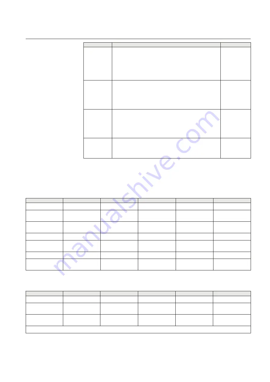
Server
TCP/UDP -
port
Defines the TCP or UDP port that masters can form connections
to. Default Modbus TCP/IP communication port is 502. If
multiple Modbus gateways are running on same device (for both
serial ports) the TCP/UDP communication ports must not be
same. For example, ports 502 and 504 can be used. The
network and the device's firewalls must enable TCP or UDP
communication for that port.
1...32500
Max. number
of clients
Defines how many network masters can be connected to the
device simultaneously. The recommended value is at least 2
when using TCP communication. Otherwise if the device does
not recognize a partially closed connection, forming new
connections is not accepted by the device the time set in
parameter “Connection idle timeout” is elapsed.
0...20
Connection
idle timeout
If there has not been communication on this route during given
amount of seconds, the device automatically closes the TCP
connection to slave and therefore frees the slave’s
communication resources. This is especially useful when
multiple masters access the same slave. The recommended
setting is about two times the polling interval of the master.
0...32500
Enable
keepalive
Defines if connection testing is performed by sending TCP
keepalive packets at certain intervals. enabled for TCP network
communication. If set to “Yes”, testing the TCP connection with
slave is enabled.
No, Yes
10.5
Modbus register maps
Table 18:
Modbus register map for IO-1 (8DI+2DO)
Function code (Hex) Function
Address range
Number of registers
Modicon notation
Properties
1 (0x01)
Read Coils
0…1
2
00001…00002
Read digital outputs
2 (0x02)
Read Discrete
Inputs
0…7
8
10001…10008
Read digital inputs
3 (0x03)
Read Multiple
Holding Registers
0…7
8
40001…40008
Read input counters
5 (0x05)
Write Single Coil
0…1
2
00001…00002
Write digital output
6 (0x06)
Write Single
Holding Register
0…7
8
40001…40008
Clear input counter
15 (0x0F)
Write Multiple Coils
0…1
2
00001…00002
Write digital outputs
16 (0x10)
Write Multiple
Holding Registers
0…7
8
40001…40008
Clear input counters
Table 19:
Modbus register map for IO-2 (6DI+4DO+2AI)
Function code (Hex) Function
Address range
Number of registers
Modicon notation
Properties
1 (0x01)
Read Coils
0…3
4
00001…00004
Read digital outputs
2 (0x02)
Read Discrete
Inputs
0…5
6
10001…10006
Read digital inputs
3 (0x03)
Read Multiple
Holding Registers
0…5
6
40001…40006
Read input counters
Table continues on next page
1MRS758458 F
Section 10
Modbus application settings
ARR600
47
User Manual


