I/O port: I/O port:
0xA35 (base address)
for Control Register (Read 0xF2h bit 3)
0xA36 (base address)
for Control Data Value
7
6
5
4
3
2
1
0
X
X
X
X
Ignition
X
X
X
Status
0 = Ignition off
1 = Ignition on
Debug Command Line
- O A35 F2
-
I A36 // Check Bit 3 Status
4.2 WDT Setting
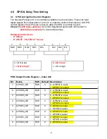
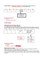
I/O port:
A10 (base address) + 05h and
06h
1 Watchdog Timer Control Register
The Watchdog Timer Control Register controls the WDT working mode. Write the value to
the WDT Configuration Port. The following table describes the Control Register bit definition:
7
6
5
4
3
2
1
0
0
0
1
1
Timer
0
Select output
Unit
pulse width of
RSTOUT#
0
= 1 sec
00
= 1 ms
1
= 60 sec *
01
= 25 ms
10
= 125 ms*
11
= 5 sec
Debug Command Line
-
O A16 05
-
O A15 32
// 5 sec // 3A
5 m in u te s
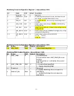
Watchdog Timer Function
Watch dog timer is provided for system controlling. If time-out can trigger one signal to
high/low level/pulse, the signal is depend on register setting.
The time unit has two ways from 1sec or 60sec. In pulse mode, there are four pulse widths
can be selected (1ms/25ms/125ms/5sec). Others, please refer the device register description
as below.
10

