background image

Setup 

Document No. D106-009  


Page 29 of 76 

Revision 1.15  

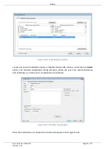
The second part of the Reactive Tag mode is to configure the link between a Modbus function 
and register range to a Logix tag. This will allow the Modbus message initiator to effectively 
write to, or read from, a Logix tag using traditional Modbus functions. 


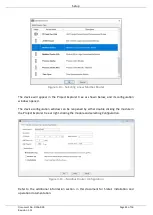
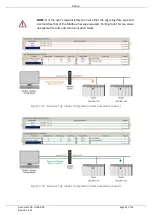
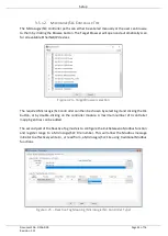
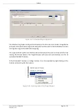
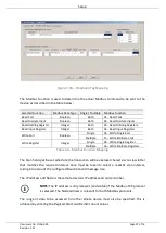
Figure 3.20 – Reactive Tag Mapping (Logix Controller Type) 

 
Modbus read and write functions involve the transfer of either Booleans or integers (16 bit).  
A part or combination of integers may represent other types. For this reason, the Modbus 
Router allows the mapping of integer based functions to the following Logix data types when 
using a ControlLogix or CompactLogix controller: 


SINT 


INT 


DINT 


REAL  

All discrete or Boolean based function need to be mapped to a Logix BOOL array. 
 

NOTE

: When mapping a range of registers to a Logix array, it is important to 

ensure that the destination Logix array is sufficiently large to accommodate all 
the data. 
  

NOTE

: When mapping a range of registers to a Logix DINT or REAL array, the 

Register  Start  must  be  an  even  number,  else  the  integer  data  will  not  be 
aligned with the 32-bit destination Logix tag. 
 

NOTE

: When writing to a DINT or REAL datatype the user cannot write a single 

Modbus  element  (16-bit).  At  least  two  elements  will  need  to  be  written  to 
either of the above 32-bit datatypes (DINT or REAL). 
 

Summary of Contents for A-MBR

Page 1: ...Modbus Router Modbus Router 485 User Manual A MBR A MBR 485 Document No D106 009 12 2017 Revision 1 15 ...

Page 2: ...ination 15 2 7 Ethernet Port 16 3 Setup 17 3 1 Install Configuration Software 17 3 2 Network Parameters 17 3 3 Creating a New Project 22 3 4 Modbus parameters 24 3 5 Message Routing 27 3 5 1 Reactive Tag Mode 27 3 5 2 Scheduled Tag Mode 34 3 5 3 Unscheduled Mode 39 3 6 Module Download 40 3 7 RSLogix 5000 Configuration 42 3 7 1 Studio 5000 Configuration Version 20 42 3 7 2 RSLogix 5000 Configuratio...

Page 3: ...cs 59 5 1 LEDs 59 5 2 Module Status Monitoring in Slate 60 5 3 Modbus Diagnostics 65 5 4 Modbus Packet Capture 66 5 5 Module Event Log 69 5 6 Web Server 70 6 Technical Specifications 71 6 1 Dimensions 71 6 2 Electrical 72 6 3 Ethernet 72 6 4 Serial Port RS232 73 6 5 Serial Port RS485 73 6 6 Modbus 73 6 7 Certifications 74 Index 75 ...

Page 4: ...ean 32 bit alignment to be for single and multiple Coil Discrete Register updates 1 7 13 May 2016 Add ODVA Conformance mark 1 8 26 June 2016 Updated temperature range 1 9 8 August 2016 Added EDS Add On Profile Added Modbus Diagnostic functions Added RoHS2 compliant to certifications 1 10 23 May 2017 Add support for two additional interface modes Add RCM Conformance mark 1 11 5 October 2017 Add UL ...

Page 5: ...uter can communicate on serial RS232 The Modbus Router allows the user to integrate Modbus devices into a Rockwell Logix platform e g ControlLogix CompactLogix MicroLogix etc with minimal effort Figure 1 1 Typical Setup 1 2 FEATURES The Modbus Router is able to transfer data from various Modbus devices to a maximum of three Logix controllers The module operates in one of three modes simplifying th...

Page 6: ... and output assemblies will provide additional diagnostics information which will be available in the Logix controller environment The Modbus Router allows the user to integrate Modbus devices into a Logix system with minimal effort No copying or mapping of data in the Logix controller is required as the Modbus Router writes directly into Logix tags The module also provides a range of statistics a...

Page 7: ...ing and redirecting serial Modbus messages from legacy devices to EtherNet IP the module provides an interface for data exchange to Allen Bradley ControlLogix and CompactLogix platforms This enables user to replace legacy devices and systems with minimal effort and downtime The Modbus Router allows a Logix platform to seamlessly integrate into a Modbus network with Reactive Tag Mode The module wil...

Page 8: ...municating to a number of remote Modbus devices e g Electrical Protection Units or Remote Terminal Units may find the Modbus Router useful when operating in Scheduled Tag Mode as shown in the figure above The module acting as a Modbus master will exchange data between the Modbus device and Logix platform at a configured interval without any need for additional coding or mapping ...

Page 9: ...ring standard www cisco com c en us td docs video cds cde cde205_220_420 installation guide cde205_220_420_hig Connectors html CIP Routing The CIP Networks Library Volume 1 Appendix C Data Management Modbus http www modbus org Table 1 2 Additional Information 1 5 SUPPORT Technical support is provided via the Web in the form of user manuals FAQ datasheets etc to assist with installation operation a...

Page 10: ... standards which can be found in the additional information section of this document When using the RS232 version the RS232 port uses a four way connector This provides connection for the communication transmit TX receive RX and ground GND conductors The fourth connection earth is used for shielding the cable in high noise environments Figure 2 1 Modbus Router RS232 side and bottom view When using...

Page 11: ...LEDs as shown in the front view figure below These LEDs are used to provide information regarding the module system operation the Ethernet interface and the auxiliary communication interface RS232 or RS485 Figure 2 3 Modbus Router front and top view The module provides four DIP switches at the top of the enclosure as shown in the top view figure above ...

Page 12: ...d the application firmware and will wait for new firmware to be downloaded This should only be used in the rare occasion when a firmware update was interrupted at a critical stage DIP Switch 2 This will force the module into DHCP mode which is useful when the user has forgotten the IP address of the module DIP Switch 3 Reserved DIP Switch 4 Reserved Table 2 1 DIP Switch Settings ...

Page 13: ... specification The DIN rail clip is mounted on the bottom of the module at the back as shown in the figure below Use a flat screw driver to pull the clip downward This will enable the user to mount the module onto the DIN rail Once the module is mounted onto the DIN rail the clip must be pushed upwards to lock the module onto the DIN rail Figure 2 5 DIN rail mouting ...

Page 14: ...receive RX and GND conductors for serial communication The shield terminal can be used for shielded cable in high noise environments NOTE The shield of the RS232 port is internally connected to the power connector earth Thus when using a shield it is important to connect the Earth terminal on the power connector to a clean earth Failing to do this can lower the signal quality of the RS232 communic...

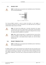
Page 15: ... a clean earth Failing to do this can lower the signal quality of the RS485 communication NOTE When using a shielded cable it is important that only one end of the shield is connected to earth to avoid current loops It is recommended to connect the shield to the Modbus Router module and not to the other Modbus device 2 6 RS485 TERMINATION NOTE The RS485 port is only applicable with the RS485 versi...

Page 16: ...cument No D106 009 Page 16 of 76 Revision 1 15 2 7 ETHERNET PORT The Ethernet connector should be wired according to industry standards Refer to the additional information section in this document for further details ...

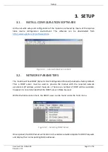
Page 17: ... module will have DHCP Dynamic Host Configuration Protocol enabled as factory default Thus a DHCP server must be used to provide the module with the required network parameters IP address subnet mask etc There are a number of DHCP utilities available however it is recommended that the DHCP server in Slate be used Within the Slate environment the DHCP server can be found under the Tools menu Figure...

Page 18: ...assign an IP address click on the corresponding Assign button The IP Address Assignment window will open Figure 3 4 Assigning IP Address The required IP address can then be either entered or a recently used IP address can be selected by clicking on an item in the Recent List If the Enable Static checkbox is checked then the IP address will be set to static after the IP assignment thereby disabling...

Page 19: ...ack to Off position to avoid the module returning to a DHCP mode after the power is cycled again If the module s DIP switch 2 is in the On position during the address assignment the user will be warned by the following message Figure 3 6 Force DHCP warning In addition to the setting the IP address a number of other network parameters can be set during the DHCP process These settings can be viewed ...

Page 20: ...electing the Target Browser The Target Browser automatically scans the Ethernet network for EtherNet IP devices Figure 3 8 Target Browser Right clicking on a device reveals the context menu including the Port Configuration option Figure 3 9 Selecting Port Configuration ...

Page 21: ...Revision 1 15 All the relevant Ethernet port configuration parameters can be modified using the Port Configuration window Figure 3 10 Port Configuration Alternatively these parameters can be modified using Rockwell Automation s RSLinx software ...

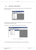
Page 22: ...he File menu select New Figure 3 11 Creating a new project A Slate project will be created showing the Project Explorer tree view To save the project use the Save option under the File menu A new device can now be added by selecting Add under the Device menu Figure 3 12 Adding a new device In the Add New Device window select the Modbus Router and click the Ok button ...

Page 23: ...ow and its configuration window opened The device configuration window can be reopened by either double clicking the module in the Project Explorer tree or right clicking the module and selecting Configuration Figure 3 14 Modbus Router configuration Refer to the additional information section in this document for Slate s installation and operation documentation ...

Page 24: ...e Tag mode In Reactive Tag mode the module will automatically route the Modbus message and function to the appropriate pre configured Logix tag Modbus communication in this mode is initiated by the remote Modbus device Scheduled Tag mode In Scheduled Tag mode the Modbus Router will initiate the exchange between the remote Modbus device and Logix Either by reading data from a Modbus device and writ...

Page 25: ...al configuration parameters The general configuration is shown in the figure below The Modbus general configuration window is opened by either double clicking on the module in the tree or right clicking the module and selecting Configuration Figure 3 15 General Configuration The Modbus configuration consists of the following parameters Parameter Description Protocol The Modbus Router can interface...

Page 26: ...able 3 2 Modbus configuration parameters The Modbus Router can be configured to operate in one of two Base Address modes Modbus Base 0 or PLC Base 1 For example when operating in Base 0 mode the first holding register address will be 40000 whilst in Base 1 mode the first holding register address will be 40001 Depending on the system being interfaced to the user will need to select the correct opti...

Page 27: ...s In this mode the Modbus Router will redirect a Modbus message to a Logix controller at a preconfigured path Thus the routing of Modbus read and write register requests is managed by the Modbus Router and converted to direct Logix tag read and write functions Figure 3 17 Reactive Tag mode configuration The Reactive Tag mode is configured in two steps First the user must create a Target Name CIP p...

Page 28: ...can for all available EtherNet IP devices If the Ethernet IP module is a bridge module it can be expanded by right clicking on the module and selecting the Scan option Figure 3 18 Scanning node in the Target Browser Figure 3 19 Target Browser selection The required Logix controller can then be chosen by selecting it and clicking the Ok button or by double clicking on the controller module A maximu...

Page 29: ...ng of integer based functions to the following Logix data types when using a ControlLogix or CompactLogix controller SINT INT DINT REAL All discrete or Boolean based function need to be mapped to a Logix BOOL array NOTE When mapping a range of registers to a Logix array it is important to ensure that the destination Logix array is sufficiently large to accommodate all the data NOTE When mapping a ...

Page 30: ...tag selection The Target Tag can be either entered manually or selected using the Tag Browser in Slate The Tag Browser requires the controller to be available on the network To browse to the tag click on the Browse button The Tag Browser will open and scan all the tags inside that controller If the controller has been recently scanned in this Slate session then a cached version of the tags will be...

Page 31: ...nsure that the Logix tag data type and size matches that of the Modbus message requests Failing to do this can cause unexpected results and communication faults Figure 3 22 Reactive Tag mode configuration in Slate example route 1 Figure 3 23 Reactive Tag mode configuration in Slate example route 2 ...

Page 32: ...e required MicroLogix SLC controller can then be chosen by selecting it and clicking the Ok button or by double clicking on the controller module A maximum number of 3 controller mapping entries can be added The second part of the Reactive Tag mode is to configure the link between a Modbus function and register range to a MicroLogix SLC File number This will allow the Modbus message initiator to e...

Page 33: ...e array the Register Start must be an even number else the integer data will not be aligned with the 32 bit destination Float File NOTE When writing to a REAL datatype the user cannot write a single Modbus element 16 bit At least two elements will need to be written a float datatype NOTE When doing a single multiple coil discrete write to a MicroLogix SLC Bool array datatype the remaining bits of ...

Page 34: ...odbus Router when in the Scheduled Tag mode initiates the messaging In this mode the Modbus Router transfers data between a Logix controller and Modbus devices without any configuration or programming required in either the Modbus device or the Logix controller The data will be exchanged at a fixed interval which is configured in Slate NOTE When the user has selected the MicroLogix SLC Controller ...

Page 35: ...link the Modbus function and register range to the destination Logix tag The Logix controller paths can either be entered manually or the user can browse to them by clicking the Browse button The Target Browser will open and automatically scan for all available EtherNet IP devices If the Ethernet IP module is a bridge module it can be expanded by right clicking on the module and selecting the Scan...

Page 36: ...e Scheduled Tag mode setup is to configure the scan intervals The scan intervals allow different data items to be transferred at different rates There are 4 scan classes viz A B C and D The intervals for each can be adjusted by entering the scan time in milliseconds The interval must be between 200 milliseconds and 60 seconds The third part of the Scheduled Tag mode setup is to configure the link ...

Page 37: ...Multiple Coils Write Register Integer Single 06 Write Single Register Multiple 16 Write Multiple Registers Table 3 3 Modbus Function Mapping The Scan field specifies at what rate the transaction will be executed Select a scan class letter that matches the required interval Care must be taken to select a realistic scan interval taking into account the configured Baud rate and message size The IP ad...

Page 38: ...L datatype the user cannot write a single Modbus element 16 bit At least two elements will need to be written to either of the above 32 bit datatypes DINT or REAL NOTE When doing a single multiple coil discrete write to a Logix Bool array datatype the remaining bits of the 32 bit aligned Bool array will be overwritten One of the Target Names configured in the first step can be selected by means of...

Page 39: ... tag selection 3 5 3 UNSCHEDULED MODE There is no additional configuration required when using the Unscheduled Mode The configuration required for the Modbus message is contained within the Message Block data configured in Logix Refer to the operation section for more information ...

Page 40: ...ss of the module as set in the module configuration It can however be modified if the Modbus Router is not on a local network The Connection path can be set by right clicking on the module and selecting the Connection Path option Figure 3 32 Selecting Connection Path The new connection path can then be either entered manually or selected by means of the Target Browser Figure 3 33 Connection Path T...

Page 41: ...g the download process the module s time will be compared to that of the PC s time Should the difference be greater than 30 seconds the user will be prompted to set the module time to that of the PC time Figure 3 36 Setting module time The module time is used only for the event log Within the Slate environment the module will be in the Online state indicated by the green circle around the module ...

Page 42: ...ust be added using a Generic Profile which is described in section 3 7 2 3 7 1 STUDIO 5000 CONFIGURATION VERSION 20 Integration with the Logix family in Studio5000 makes use of the EDS AOP Before the module can be added to the tree the module s EDS file must be registered Using RSLinx the EDS file can be uploaded from the device after which the EDS Hardware Installation tool will be invoked to com...

Page 43: ...n be added to the Logix IO tree in Studio 5000 Under a suitable Ethernet bridge module in the tree select the Ethernet network right click and select the New Module option Figure 3 39 Adding a module The module selection dialog will open To find the module more easily use the Vendor filter to select only the Aparian modules as shown in the figure below ...

Page 44: ...us Router or Modbus Router 485 module and select the Create option The module configuration dialog will open where the user must specify the Name and IP address as a minimum to complete the instantiation Figure 3 41 Module instantiation Once the instantiation is complete the module will appear in the Logix IO tree ...

Page 45: ...gix IO tree The Module Defined Data Types will automatically be created during the instantiation process These data types provide meaningful structures to the module data An excerpt of the Input Image is shown in the following figure Figure 3 43 Module Defined Data Type ...

Page 46: ...t Bridge in the RSLogix 5000 and selecting New Module after which the ETHERNET MODULE is selected to be added as shown in the figure below NOTE See the next section for importing the configuration L5X Figure 3 44 Add a Generic Ethernet Module in RSLogix 5000 The user must enter the IP address of the Modbus Router that will be used The assembly instance and size must also be added for the input out...

Page 47: ...is document for further details on the limits of the RPI NOTE Although the module is capable of running with an RPI of 10ms it is recommended to set the RPI to 500ms to avoid unnecessary loading of the module processor Figure 3 46 Connection module properties in RSLogix 5000 Once the module has been added to the RSLogix 5000 IO tree the user must assign the User Defined Types UDTs to the input and...

Page 48: ...UTINES To simplify the mapping of the input image an RSLogix 5000 Routine Partial Import L5X file is provided This file can be imported by right clicking on the required Program and selecting the Import Routine option Figure 3 48 RSLogix 5000 Importing Modbus Router specific routine and UDTs Figure 3 49 Selecting partial import file ...

Page 49: ...e to the aforementioned tags An example Unscheduled Message instruction with the associated Tags The user may need to change the routine to map to the correct Modbus Router module instance name and make sure that the mapping routine is called by the Program s Main Routine Figure 3 50 Imported RSLogix 5000 objects Refer to the additional information section of this document for an example RSLogix 5...

Page 50: ...the mapping is routing the Modbus messages correctly Refer to the diagnostics section of this document for a more detailed explanation of the various indicators that can be used to diagnose the module 4 2 RSLOGIX 5000 ASSEMBLIES When the module operates in a Logix owned mode the Logix controller will establish a class 1 cyclic communication connection with the Modbus Router A input and output asse...

Page 51: ...er Datatype Description Instance STRING This parameter is the instance name of the module that was configured under the general Modbus configuration in Slate Status ReactiveTagMode BOOL Set if the module is operating in Reactive Tag mode Status ScheduledTagMode BOOL Set if the module is operating in Scheduled Tag mode Status UnscheduledMode BOOL Set if the module is operating in Unscheduled mode ...

Page 52: ...etCount DINT The number of Modbus packets sent by the module ModbusChecksumErrors DINT The number of corrupted Modbus packets received by the module ModbusTimeout DINT The number of timed out Modbus packets sent by the module Thus no reply was received ModbusUnspecifiedErrors DINT The number of Modbus errors not defined in any other statistic TagReads DINT The total number of Logix tag reads execu...

Page 53: ... in Unscheduled Mode it will process Modbus message requests sent from Logix via a message instruction NOTE The user will need to build some of the Modbus request data of the unscheduled message NOTE When in unscheduled mode the Controller Type selection in the General configuration will not be applicable The Modbus Router will only support a Logix Controller type in unscheduled mode To simplify t...

Page 54: ...vice Code 6A Hex Unscheduled Modbus Pass through Class 40E Hex Instance 1 Attribute 0 Source Element The request tag instance Must follow the structure of the AparianModbusMessageRequest UDT Source Length 272 Destination Element The response tag instance Must follow the structure of the AparianModbusMessageResponse UDT Table 4 3 Message Configuration Paramaters ...

Page 55: ...tion can be used to select the path Alternatively enter the CIP path in the format 1 X 2 IP where 1 represents the backplane port X represents the slot of the Ethernet bridge module 2 represents the Ethernet port of the Ethernet bridge module and IP represents the IP address of the Modbus Router e g 1 1 2 192 168 1 41 The request tag e g ModbusMessageRequest should be configures as follows Figure ...

Page 56: ...ding the function code but preceding the checksum See the example further on in the chapter Table 4 4 Unscheduled Message Request Parameters Figure 4 7 Unscheduled Message Response Tag Parameter Description Status The Modbus exception code returned A zero represents success See the table below for common exception codes Response Length Length of the response data received Response Data Response to...

Page 57: ... Queue Table 4 6 Common Modbus Functions The following table shows common Status Exception codes Code Modbus Exception 0 Success 1 Illegal Function 2 Illegal Data Address 3 Illegal Data Value 4 Server Device Failure 5 Acknowledge 6 Server Device Busy 8 Memory Parity Error 10 Gateway Path Unavailable 11 Gateway Target Device Failed to Respond Table 4 7 Common Exception Codes 4 3 1 EXAMPLE In the fo...

Page 58: ...Operation Document No D106 009 Page 58 of 76 Revision 1 15 The standard ModbusMessageRequest structure is populated as shown in the figure below Figure 4 8 Modbus Message Request Example ...

Page 59: ...ing correctly For example if the module application firmware has been corrupted or there is a hardware fault the module will have a red Module LED If the LED is green then the module has booted and is running correctly Act The activity LED is used for the RS232 or RS485 serial port Every time there is a successful Modbus routing transaction the LED will flash green The LED will flash red if the ro...

Page 60: ...ust be online If the module is not already Online following a recent configuration download then right click on the module and select the Go Online option Figure 5 5 2 Selecting to Go Online The Online mode is indicated by the green circle behind the module in the Project Explorer tree Figure 5 5 3 Selecting online Status The Status monitoring window can be opened by either double clicking on the ...

Page 61: ...ing Indicates whether the routing of module is enabled or inhibited The routing operation can be inhibited in the output assembly of the module Transaction Rate The transaction rate is the number of Modbus messages per second that the module is currently routing Up Time Indicates the elapsed time since the module was powered up Module Time Indicates the module s internal time The module time is st...

Page 62: ...The Modbus Statistics tab displays the statistics associated with the Modbus communication and mapping Statistic Description Tx Packet Count The number of Modbus packets sent by the module Rx Packet Count The number of Modbus packets received by the module Checksum errors The number of corrupted Modbus packets received by the module Parity errors The number of bytes with parity errors received by ...

Page 63: ...mber of times the Modbus device responded with a Device Failure exception Acknowledge Response Delay The number of times the Modbus device responded with an Acknowledge exception Slave Device Busy The number of times the Modbus device responded with a Slave Busy exception Negative Acknowledge The number of times the Modbus device responded with a Negative Acknowledge exception Memory Parity Error ...

Page 64: ... of the Logix tag being set to either None or Read Only Tag Reads The number of tag read transactions executed by the Modbus Router module Tag Writes The number of tag write transactions executed by the Modbus Router module ENIP Retries This count increases when no response was received from the Logix Controller by the time the ENIP timeout is reached ENIP Failures This count increases when the EN...

Page 65: ...splay the successful packet counts processed by each mapping item If an item count changes then the success count field will be displayed with a green background for approximately 3 seconds This provides quick visual feedback as to which items are currently active The fields in the map items will adjust to suite the appropriate mode No items are displayed in Unscheduled mode Figure 5 8 Map Item st...

Page 66: ...esponse Count 16 Return Server NAK Count 17 Return Server Busy Count 18 Return Bus Character Overrun Count 20 Clear Overrun Counter and Flag Table 5 6 Tag Mapping statistics These sub functions are static objects which will always return a value of zero They are supported in the Modbus Router for certain legacy systems requiring access to these sub functions 5 4 MODBUS PACKET CAPTURE The module pr...

Page 67: ...9 Selecting Modbus Packet Capture The Modbus Packet Capture window will open and automatically start capturing all Modbus packets Figure 5 10 Modbus packet capture To display the captured Modbus packets the capture process must first be stopped by pressing the Stop button ...

Page 68: ...alid Modbus constructs and valid checksums Dirn The direction of the packet either transmitted Tx or received Rx Node Modbus node address of the message destination Description A brief description of the packet showing the function and register range if applicable Data The raw packet data Table 5 7 Modbus Packet Capture fields The packet capture can be saved to a file for further analysis by selec...

Page 69: ...olatile memory and can be displayed using Slate or via the web interface To view them in Slate select the Event Viewer option in the Project Explorer tree Figure 5 13 Selecting the module Event Log The Event Log window will open and automatically read all the events from the module The log entries are sorted so as to have the latest record at the top Custom sorting is achieved by double clicking o...

Page 70: ...tion under the tools menu 5 6 WEB SERVER The Modbus Router provides a web server allowing a user without Slate or RSLogix 5000 to view various diagnostics of the module This includes Ethernet parameters system event log advanced diagnostics and application diagnostics Modbus diagnostics NOTE The web server is view only and thus no parameters or configuration can be altered from the web interface F...

Page 71: ... 76 Revision 1 15 6 TECHNICAL SPECIFICATIONS 6 1 DIMENSIONS Below are the enclosure dimensions as well as the required DIN rail dimensions All dimensions are in millimetres Figure 6 6 1 Modbus Router enclosure dimensions Figure 6 6 2 Required DIN dimensions ...

Page 72: ...ssions IEC61000 6 4 ESD Immunity EN 61000 4 2 Radiated RF Immunity IEC 61000 4 3 EFT B Immunity EFT IEC 61000 4 4 Surge Immunity Surge IEC 61000 4 5 Conducted RF Immunity IEC 61000 4 6 Table 6 1 Electrical specification 6 3 ETHERNET Specification Rating Connector RJ45 Conductors CAT5 STP UTP ARP connections Max 20 TCP connections Max 20 CIP connections Max 10 Communication rate 10 100Mbps Duplex m...

Page 73: ...t specification 6 5 SERIAL PORT RS485 Specification Rating RS485 Connector 4 way terminal RS485 Conductor 24 18 AWG BAUD 1200 2400 4800 9600 19200 38400 57600 115200 Parity None Even Odd Data bits 8 Stop bits 1 Table 6 4 RS485 Serial Port specification 6 6 MODBUS Specification Rating Reactive Tag mode Max 40 mapping items Scheduled Tag mode Max 40 mapping items Application Functions Supported Read...

Page 74: ...vision 1 15 Protocols Modbus RTU Modbus TCP Table 6 5 Modbus specification 6 7 CERTIFICATIONS Certification Mark CE Mark UL Mark File E494895 CLASS 1 DIV 2 GROUPS A B C D ODVA Conformance MBR F W 1 009 MBR485 F W 1 004 RoHS2 Compliant RCM Table 6 6 Certifications ...

Page 75: ...2 54 Logix Tag Map 27 30 M Mapping Mode 24 MODBUS 1 5 6 7 8 9 10 11 14 15 22 23 24 25 26 27 29 30 31 32 33 34 35 36 38 39 40 46 49 50 51 52 53 54 55 56 57 58 59 60 61 62 63 64 65 66 67 68 69 70 72 73 MODBUS general configuration 25 MODBUS parameters 24 Modbus Router 5 6 7 8 9 10 11 14 15 22 23 24 25 27 34 40 46 49 50 53 55 56 59 60 64 68 69 70 O output assembly 50 52 53 61 P Protocol 17 25 R React...

Page 76: ...Index Document No D106 009 Page 76 of 76 Revision 1 15 transmit TX 10 14 15 U UDTs 9 47 48 49 50 53 Unscheduled 6 24 27 39 49 51 53 54 55 56 61 64 User Defined Types UDTs 47 W web server 60 69 ...

Reviews: