Setup
Document No. D106-009
Page 37 of 76
Revision 1.15
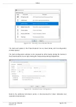
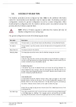
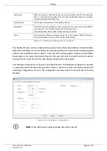
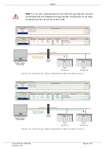
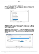
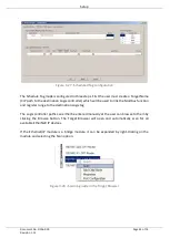
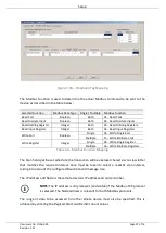
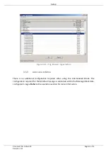
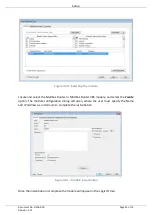
Figure 3.30 – Scheduled Tag Mapping
The Modbus Function is used to determine the actual Modbus command to be sent to the
device, as described in the table below:
Selected Function
Modbus Data Type Single / Multiple Modbus Function
Read Coil
Boolean
Both
01 - Read Coils
Read Discrete Input
Boolean
Both
02 - Read Discrete Inputs
Read Holding Register
Integer
Both
03 - Read Holding Registers
Read Input Register
Integer
Both
04 - Read Input Registers
Write Coil
Boolean
Single
05 - Write Single Coil
Multiple
15 - Write Multiple Coils
Write Register
Integer
Single
06 - Write Single Register
Multiple
16 - Write Multiple Registers
Table 3.3 - Modbus Function Mapping
The Scan field specifies at what rate the transaction will be executed. Select a scan class letter
that matches the required interval. Care must be taken to select a realistic scan interval,
taking into account the configured Baud rate and message size.
The IP address and Node is the remote device’s IP address and node number.
NOTE:
The IP address is only relevant (and visible) if the Modbus-TCP protocol
is selected. The Node address is relevant for both Modbus protocols.
The range of data to be accessed from the remote device must also be specified. This is
achieved by entering the
Register Start
and
Element Count
values.

