11
32094B–AVR32–05/09
AVR32710
6.2.1
Pulse Width Modulation Generation
6.2.1.1
Using PWM module
The AVR32 UC3 is able to generate PWM signals through a dedicated PWM module or through
the Timer Counter used. The PWM module is used in this application
(1)
.
•
We need first to setup alternate functions of GPIO corresponding to alternate pins/functions
used for PWM channels.
•
PWM module is configured in center aligned mode or left aligned mode. We will only
consider PWM module in center aligned mode to fit with S.V.P.W.M implementation. To
configure this mode, we need to set:
–
CALG bifield in CMRx register at ‘1’ (fixed value)
•
The PWM module has its own global prescaler.
–
PREA,PREB bitfield in PWM.MR register
•
Each PWM channels has its own prescaler as well. It is possible to define a different period
for a given channel
x
.
–
CPRE bitfield in PWM.CMR
x
register
•
The PWM period and duty cycle is configured from this prescaled period:
–
CPRD bitfield in CMRx register
–
CDTY bitfield in CMRx register
•
Finally enable PWM channel
–
CHIDx id in ENA register
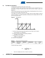
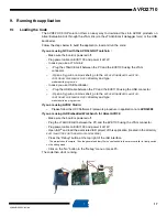
Figure 6-3.
PWM Channel in center aligned mode
Let’s take the following example:
1.
Refer to UC3 datasheet section PWM for more details
Table 6-2.
PWM calculation example
PBA(MHz)
CMRx.CPRE
MR.DIVA
MR.DIVB
CPRDx
PWM(Hz)
24
1
0
0
256
23437
CounterValue
Value
CDTY
PWMx
PWM in
Center Aligned Mode
UH
UL
YH
YL
ZL
ZH
HallA
HallB
HallC
BLDC
Hall Sensors
CPRD
)
(
2
s
PBA
CPRDxDIVA
PERIOD
×
=


