7
32094B–AVR32–05/09
AVR32710
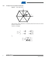
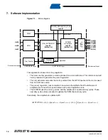
It implies as well that switching configuration tables could be expressed in (d-q) format
Each space vector corresponding to WH,VH and UH could be expressed as a combination of
Vds and Vqs (vector list in
). This mean for example (WH,VH,UH)=(1,0,0)=V5
5.2.3
Stepping increment and sampling frequency
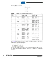
In this case, it is possible to define any stator voltage as:
With
As shown in
, the angle decomposes every step of Space Vector computation algo-
rithm. As the expression of stator voltage is identical in all the 6 sectors, it is possible to only
compute equation (1) and (2).
But, every step in computation is given for a angular frequency (in cycles/sec) :
The Ftick is defined as the sampling frequency or the basic frequency of the application. n is the
angle stepping increment from the range
For example, with a frequence of tick equal to 20KHz and a resolution up to 8 bits,it is possible
to define a step range from [0;78] thus an angle precision of 0.77 degree.
As the UC3 family has DSP instructions support, the sinus and cosinus computation will be done
in software for SVPWM and not with a lookup table. Thus, it is possible to define a specific reso-
lution for an application.
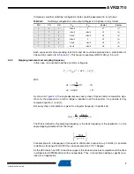
Table 5-2.
Switching configurations and output voltages of a 3-phase in (d-q) format
WH
VH
UH
V
ds
V
qs
Vector
Sector
0
0
1
2Vdc/3
0
V1
(1)
1
1
0
+Vdc/3
+Vdc/3
V2
(2)
0
1
0
-Vdc/3
+Vdc/3
V3
(3)
1
1
0
-2Vdc/3
0
V4
(4)
1
0
0
-Vdc/3
-Vdc/3
V5
(5)
1
0
1
Vdc/3
-Vdc/3
V6
(6)
y
y
x
s
U
d
dxU
e
V
V
+
=
=
θ
max
)
2
(
)
sin(
)
1
(
)
3
sin(
θ
θ
=
−
Π
=
dy
dx
n
Ftick
n
resolution
×
×
Π
=
2
3
)
(
θ
⎥
⎥
⎦
⎤
⎢
⎢
⎣
⎡
resolution
Ftick
2
;
0


