AVR1605
3
8242A-AVR-05/09
2 Getting up and running
This section walks you through the basic steps for getting up and running, by setting
up the hardware. The necessary setup and requirements are described along with
relevant information.
2.1 Hardware Setup
This section gives the step by step procedure to setup the hardware for the
experiment.
The Boot Loader software presented in this application note uses the AVR Open
Source Programmer (AVROSP) as the user interface. The example application
implements functions to read or update the Flash and EEPROM memories on the
target device. It is also possible to read and update the Lock bits and read the Fuse
bits of the device using the ATxmega128A1 AVR device with STK600.
On the STK600, connect the PD2/PD3 pins to the RXD/TXD pins to route the USART
signals to the RS-232 output.
The STK600 has got two RS232 ports marked CAN (Male Type) and RS232 (Female
Type). Connect a serial cable between the PC and the RS232 (Female Type) port of
STK600.
On STK600, connect the PD4 pin to the SW0 pin to use micro switch SW0 to enable
boot loader mode.
Please refer STK600 User Guide, available in AVR Studio
®
Help to connect it with PC
and to mount the device with correct routing and socket cards combination.
2.2 System Configuration
This section gives the information about setting up your PC prior to start the
implementation.
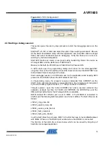
Include the xml_dev_files directory path (found in code\AVROSP_Test) to the
windows PATH by creating a variable name and value. This is set because the
system will search the default locations for the AVROSP.exe file to run from any
location of the directory. If this is not done, then you can use AVROSP.exe in the
folder where it is and you can not call it anywhere else. It can be set by right clicking
My Computer icon and selecting the Properties option as demonstrated in the Figure
2.2-1, 2, 3 below. (You may need to restart the computer to enable the changes).

