IPC@CHIP SC2x3
Hardware Manual V1.02 [01.03.09]
©2000-2009 BECK IPC GmbH
Page 29
6.2.2 Usage of PIO0..PIO3 in consideration of UART1 (Bootloader interface)
The RTOS version can be updated via UART1 and the Ethernet interface.
In some rare cases a system crash can corrupt the RTOS image on the flash disk. If the RTOS is damaged
and doesn’t boot anymore, a update through Ethernet will not work. Without a working RTOS it can only be
repaired by programming it through the serial bootloader interface on UART1.
For this reason the pre-installed bootloader observes UART1_TXD and UART1_RXD to recognize a RTOS
update via the program Chiptool. To do this, the bootloader initializes UART1 and the corresponding pins will
be active while booting and not high impedance!
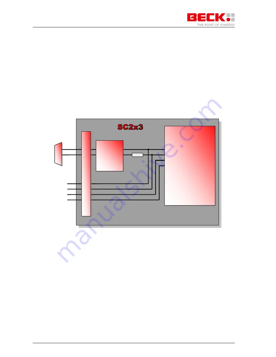
This has to be considered, if PIO0..PIO3 is used. The following figure shows a block diagram of the internal
schematic of the SC2x3.
Figure 6-1: Internal block diagram of PIO0..PIO3 and UART1
CPU
Transceiver
TXD/PIO0
RXD/PIO1
5K6
RTS/PIO2
CTS/PIO3
X1
PIO0
PIO1
PIO2
PIO3
UART1
TXD
RXD


