background image


32

  / 

33


Appendix II      Data Structure 


No 

Parameter 

Description 

Example   


Unsigned 16bit AB 

unsigned 16bit integer 

(2 byte), low byte first 

Example: 01 03 02 11 22 0D 34 

Note

HEX 2211 

DEC 8721 


Unsigned 16bit BA 

unsigned 16bit integer 

(2 byte), high byte first 

Example: 01 03 02 11 22 0D 34 

Note: HEX 1122 

DEC 4386 


Signed 16bit AB 

Signed 16bit integer 

(2 byte), low byte first 

Example: 01 03 02 11 22 0D 34 

Note: HEX 2211 

DEC 8721 


Signed 16bit BA 

Signed 16bit integer 

(2 byte), high byte first 

Example: 01 03 02 11 22 0D 34 

Note: HEX 1122 

DEC 4386 


Unsigned 32bit ABCD 

Unsigned 32bit integer   

(4 byte) 

Example: 01 03 02 11 22 33 44 C6 C3 

Note: HEX 44332211 

DEC 1144201745 


Unsigned 32bit BADC 

Unsigned 32bit integer 

(4 byte


Example: 01 03 02 11 22 33 44 C6 C3 

Note: HEX 33441122 

DEC 860098850 


Unsigned 32bit CDAB 

Unsigned 32bit integer 

(4 byte) 

Example: 01 03 02 11 22 33 44 C6 C3 

Note: HEX 22114433 

DEC 571556915 


Unsigned 32bit DCBA 

Unsigned 32bit integer 

(4 byte) 

Example: 01 03 02 11 22 33 44 C6 C3 

Note: HEX 11223344 

DEC 287454020 


Signed 32bit ABCD 

Unsigned 32bit integer 

(4 byte) 

Example: 01 03 02 11 22 33 44 C6 C3 

Note: HEX 44332211 

DEC 1144201745 


Signed 32bit BADC 

Signed 32bit integer   

(4 byte) 

Example: 01 03 02 11 22 33 44 C6 C3 

Note: HEX 33441122 

DEC 860098850 


10 


Signed 32bit CDAB 

Signed 32bit integer 

(4 byte) 

Example: 01 03 02 11 22 33 44 C6 C3 

Note: HEX 22114433 

DEC 571556915 


11 


Signed 32bit DCBA 

Signed 32bit integer 

(4 byte) 

Example: 01 03 02 11 22 33 44 C6 C3 

Note: HEX 11223344 

DEC 287454020 

Summary of Contents for TG501 Series

Page 1: ...1 33 Industrial Mini RTU TG501 Series User Guide ...

Page 2: ... any notice and BIVOCOM reserves the right to improve and change this user guide at any time Users should take full responsibility for their application of products and Xiamen Bivocom Technologies Co Ltd disclaims all warranties and liability for the accurateness completeness of the information published Global Technical Sales Support Xiamen Bivocom Technologies Co Ltd Addr Unit 1504 No A1 Buildin...

Page 3: ...is user guide before you configure and install the device This manual is compatible with below models Model Description TG501 LF Industrial LTE WCDMA RTU TG501 W Industrial WCDMA RTU TG501 M Industrial LTE CAT M1 NB IoT RTU Summary of Changes Date Version Notes Editor 27 12 2019 V1 0 Initial new version Harry Huang ...

Page 4: ...14 2 Getting Started 15 2 1 Package Checklist 15 2 2 Installation 15 2 2 1 Install SIM UIM Card 15 2 2 2 Install the terminal blocks 16 2 2 3 Fasten cellular antenna 16 2 2 4 Connect cable of power adapter to TG501 16 2 2 5 Connect TG501 to PC Laptop via RS232 16 2 2 6 Load the initial configuration 17 2 2 7 Save the configuration 17 3 Configuration Tool Setting 18 3 1 Config Tool 18 3 1 1 Basic S...

Page 5: ...5 33 Appendix I AT Commands 27 1 Basic Setting 27 2 Com Setting 27 3 Network Address 29 4 Other Settings 30 5 ADC Get 31 Appendix II Data Structure 32 ...

Page 6: ...as well as LTE CAT M1 NB IoT It has rich interfaces digital input digital output analog input relay RS232 RS485 allows you to connect to different types of sensors and equipment TG501 has rich interfaces including 2x RS232 1x RS485 3x analog input 2x digital input 2x relay output 1x power input 5 35V 1x power output 12V pulse input and TTL are customizable 1 2 Applications TG501 has been widely us...

Page 7: ...ector 1 50 Ω SMA Female or 2 Option SIM Slot 1 ESD Protection 15KV Serial Interface Connector Terminal block 3 5 mm female socket with lock Ports 2 RS232 1 for debug 1 RS485 Baud Rate 300bps to 230400bps ESD protection 8KV for RS232 15KV for RS485 Analog Input Number of Ports 3 x 16 bit AD supports 4 20mA current signal input and 0 5V voltage signal input is optional Digital Input Number of Ports ...

Page 8: ...in Mounting Desktop Wall mount DIN Rail option Environmental Operating Temperature 35 C to 75 C 31 to 167 Storage Temperature 40 C to 80 C 40 to 176 Relative Humidity 0 to 93 non condensing at 25 C 77 Ethernet Isolation 1 5 kV RMS Software Network Protocols MQTT Transparent TCP Client Server UDP Client Server Modbus Gateway Modbus RTU to Modbus TCP DNS etc Management Config Tool Cloud DMP Device M...

Page 9: ...9 11 12 16 17 18 are customizable Figure 3 I O and order Number and order of Pin No Port Definition Function Description Customizable 1 VIN Power VIN input 2 VIN Power VIN input 3 GND CH 0 debug RS232 GND 4 RXD0 CH 0 debug RS232 RX 5 TXD0 CH 0 debug RS232 TX 6 A0 RS485 A 7 B0 RS485 B 8 DI0 Digital Input 0 A1 ...

Page 10: ... ADC2 CH 2 analog input DO1 18 NC NULL reserved ADC3 19 K0 CH 0 Relay K0 20 K0 CH 0 Relay K0 21 K1 CH 1 Relay K1 22 K1 CH 1 Relay K1 1 5 2 Definition of Cables TG501 utilizes industrial terminal block so we suggest you use materials of cable 28 16AWG Definition of cable for power and RS232 are as below 1 Power Adapter Output 12VDC 1 5A Color of cable Power Output Polarity Red VIN Anode Black VIN C...

Page 11: ...er cable connection 3 RS232 Cable with DB9 female interface Color of Cable Definition of cable Corresponding DB9 M Pin Number Brown RX 2 Blue TX 3 Black GND 5 4 RS232 Cable Figure 6 RS232 cable connection 5 RS485 Cable For example RS485 water level sensor Figure 7 RS485 cable connection 6 Digital Input Wet contact ...

Page 12: ...ital input 7 Analog Input 4 20mA Figure 9 Analog input 8 Two wire current loop sensor Current 4 20mA Figure 10 2 wire current loop sensor 9 Relay Output Max switch voltage 30VDC max switch current 1A max switch power 30W ...

Page 13: ... Users can use BIVOCOM 12VDC 1 5A power adapter to supply power to the device or directly supply power to the device with DC 5 35V power supply When the user supplies power to the device with an external power supply the stability of the power supply must be ensured the ripple is less than 300mV and the instantaneous voltage does not exceed 35V and the power supply is guaranteed to be more than 4W...

Page 14: ... this device is connected to outdoor sensors rain gauge water level gauge etc we suggest you take lightning protection measures such as installing lightning arresters etc to improve the safety level of the device LED Indicator Status Description Power On Power on System Blink Device is operating Online On Device is online connecting to remote server via cellular network Error On Error alarm ...

Page 15: ...t Option Figure 13 Standard Package 2 2 Installation 2 2 1 Install SIM UIM Card TG501 supports normal SIM UIM only so if you re using a Micro SIM or Nano SIM card you may need to use a Micro SIM or Nano SIM to Normal SIM adapter Make sure your RTU is powered off then use a needle object such as a pen to push the button near the SIM tray it will flick out Put the SIM UIM card to SIM tray with right...

Page 16: ...h of signal Figure 14 Antenna interfaces 2 2 4 Connect cable of power adapter to TG501 TG501 use terminal block for connecting power cable please make sure you connect the red cable to VIN and black cable for VIN then use screwdriver to fasten the cable Please refer to item 1 5 2 Warning Incorrect connection of the power cable may cause damage of device 2 2 5 Connect TG501 to PC Laptop via RS232 U...

Page 17: ...vice initially 2 Power on TG501 and wait for a while the device will print the syslog in log column there is an indication after finished the reload 3 Now you are in configuration mode and able to change or set configurations according your demands Please refer to item 3 1 for more details Figure 15 Config tool 2 2 7 Save the configuration When you finish all the settings please click the Save but...

Page 18: ...lt is 115200 Normally it will automatically detect the right port and has linked the connection by default If not please change it accordingly Figure 16 Serial Port Setting Click Reload button to reload the initial settings from the device then you are allowed to configure all settings on the tool Click Save when settings changed Restart it to quit the configuration mode and go into work mode comm...

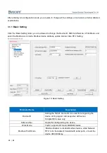
Page 19: ...vice address update interval Also RTC Setting Figure 18 Basic Setting Parameter Name Description Device ID Setting the TG501 device ID it is used for recognizing the device during register and keep alive with server 8 digital HEX value only SIM card No Helpful for distinguishing the device Work Mode TG501 supports DTU and MODEM modes Modbus Work Mode Modbus Disable to disable Modbus feature while ...

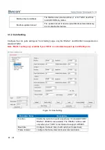
Page 20: ...com ports respectively for standard TG501 RS232 1 RS485 0 are available The RS485 1 will be valid only when your TG501 is customized to support 2 RS485 Baud rate Configure the baud rate of each serial port respectively Frame Interval configure the frame interval of serial communication Modbus Device Address The Modbus slave device address 1 is for TG501 itself that read ADC DI Relay states Modbus ...

Page 21: ...p 10 commands in total Cmd Content Edit the command content Hex Choose String or HEX to send the command Interval Time Configure the interval of command sending COM Choose Select which serial com port be applied for this command individually 3 1 3 Data center Setting You can configure the data center for each serial com ports respectively on Network Address page there are up to 5 data center can b...

Page 22: ...n channel please note that all channels cache together should less than 40KB Center Addr Port Domain name or IP address supported Com Select Choose the COM port to set Offline Data Storage Select whether to cache the data when the network fails and it works only when the Cache field being configured valid value Main or Backup Center DNS Server Addr When you use domain name for data center you need...

Page 23: ...e of cellular network LTE GSM or others FTCP Transfer Meaning Choose whether to transfer the words during communication or not If Yes the device will transfer 0xfd to 0xfd and 0xed while 0xfe to 0xfd and 0xee If No 0xfd and 0xfe perform fully transparent You can ignore this setting if you choose CTCP Custom Login data Customize the register package data and it s valid when the network protocol con...

Page 24: ... 4 20mA Upper Range The upper range of analog input refer to your sensor spec Lower Range The lower range of analog input refer to your sensor spec Input the Max Cur Vol The upper range of the sensor corresponds to the current or voltage value input Input the Min Cur Vol The lower range of the sensor corresponds to the current or voltage value input 3 2 Modbus RTU Protocol Please refer to Bivocom ...

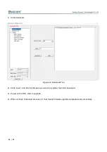
Page 25: ...ownload this software and open it 2 Click System configure the service port the same as the port of RTU TG501 of item 3 1 5 above 3 Enable the database setting configure the IP address or domain name and name of your database as well as account and password Figure 23 Service Center Software 4 Firmware Upgrade 4 1 Local Upgrade Make sure the RTU TG501 is connected to your PC via RS232 cable you can...

Page 26: ...Figure 24 Download Tool 2 Click Load and find the firmware you want to upgrade then click download 3 Power on the RTU start to upgrade 4 When it shows download success ok that means firmware upgrade completed and successfully ...

Page 27: ... 19 Example AT SIMNO 13812345678 Modbus Device Address 1 255 AT MBADDR xx Set the Modbus Device Address Xx device address Example AT MBADDR 2 Work Mode AT PROTTXT xx Set Work Mode Xx 0 DTU 1 MODEM Example AT PROTTXT 0 Modbus Update Interval AT MBUPSEC xx Xx Second value Example AT MBUPSEC 10 RTC Setting AT EXCCLK XX Example AT EXCCLK 2019 04 19 16 51 00 5 2 Com Setting Configuration Item AT Comman...

Page 28: ...bit AT COMPARITYyy xx yy 1 RS232 1 2 RS485 0 x 8N1 8E1 8O1 Example AT COMPARITY01 8E1 Command Content AT DETAILCONTyy x yy 1 10 X command content Example AT DETAILCONT03 01 03 00 00 00 22 C5 D3 hex AT DETAILCODEyy x yy 1 10 X 0 string 1 HEX Example AT DETAILCODE03 1 Interval Time AT DETAILTIMEyy x yy 1 10 X second Example AT DETAILTIME03 10 COM Choose AT DETAILCOMyy x yy 1 10 X 0 1 RS232 1 2 RS485...

Page 29: ...in Addr AT MULTISERyy xx yy 01 05 main server 06 10 backup server xx address Example AT MULTISER01 isodev picp net Port AT MULTIPORTyy xx yy 01 05 main server port accordingly 06 10 backup server port x 0 65535 Example AT MULTIPORT01 10121 Com Select AT SERCOMTYPEyy xx yy 01 05 center No xx 0 Rs232 1 1 Rs485 0 Example AT SERCOMTYPE01 1 Offline Data Storage AT SERSVOFFyy xx yy 01 05 center No xx 0 ...

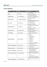
Page 30: ...x x 0 65535 second Example AT RECONSEC 10 TCP Keepalive AT KPLVMIN x x keepalive interval Example AT KPLVMIN 12 Network Selection AT NETMODE x X 0 auto 1 GSM only 2 TD SCDMA only 3 WCDMA only 4 CDMA only 5 HDR only 6 LTE only Example AT NETMODE 0 FTCP Transfer Meaning AT CONVERT x x 0 No 1 Yes Example AT CONVERT 0 Custom Login Data AT SELFLGN x X register data Example AT SELFLGN hello Custom heart...

Page 31: ...yy xx yy 01 08 ADC0 to ADC7 xx range value Example AT ADCUPPRNG01 120 Low Range AT ADCLOWRNGyy xx yy 01 to 08 ADC0 to ADC7 xx range value Example AT ADCLOWRNG01 10 Input the Max Cur Vol ATADCCURUPLyy xx yy 00 to 02 ADC0 to ADC2 xx current range 4 20mA voltage range 0 5V Example AT ADCTYPE02 0 AT ADCCURUP02 23 Input the Min Cur Vol AT ADCCURLOWyy xx yy 00 to 02 ADC0 to ADC3 xx current range 4 20mA ...

Page 32: ...EC 1144201745 5 Unsigned 32bit BADC Unsigned 32bit integer 4 byte Example 01 03 02 11 22 33 44 C6 C3 Note HEX 33441122 DEC 860098850 6 Unsigned 32bit CDAB Unsigned 32bit integer 4 byte Example 01 03 02 11 22 33 44 C6 C3 Note HEX 22114433 DEC 571556915 7 Unsigned 32bit DCBA Unsigned 32bit integer 4 byte Example 01 03 02 11 22 33 44 C6 C3 Note HEX 11223344 DEC 287454020 8 Signed 32bit ABCD Unsigned ...

Page 33: ...3 Float BADC Signed 32bit Float 4 byte Example 01 03 02 11 22 33 44 C6 C3 Note HEX33441122 Float 0 000000 14 Float CDAB Signed 32bit Float 4 byte Example 01 03 02 11 22 33 44 C6 C3 Note HEX22114433 Float 0 000000 15 Float DCBA Signed 32bit Float 4 byte Example 01 03 02 11 22 33 44 C6 C3 Note HEX11223344 Float 0 000000 ...

Reviews: