66
FX3 Programmers Manual, Doc. # 001-64707 Rev. *C
FX3 Firmware
These include APIs to
■
Initialize/de-initialize the SPI
■
Configure the SPI interface
■
Assert/deassert the SSN line
■
Set up block transfers
■
Read/write a sequence of bytes
■
Enable callbacks on SPI events
■
Register an interrupt handler
5.2.4
DMA Engine
The FX3 DMA architecture is highly flexible and programmable. It is defined in terms of sockets,
buffers, and descriptors. The complexity of programming the DMA of FX3 is eliminated by the high
level libraries.
A higher level software abstraction is provided, which hides the details of the descriptors and buffers
from the programmer. This abstraction views the DMA as being able to provide data channels
between two blocks.
■
A data channel is defined between two blocks
■
One half is a producing block and the other half is a consuming block
■
The producing and consuming blocks can be:
❐
A USB endpoint
❐
A GPIFII socket
❐
Serial interfaces such as UART and SPI
❐
CPU memory
The number of buffers required by the channel must be specified.
The following types of DMA channels are defined to address common data transfer scenarios.
5.2.4.1
Automatic Channels
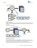
An automatic DMA channel is one where the data flows between the producer and consumer
uninterrupted when the channel is set up and started. There is no firmware involvement in the data
flow at runtime. Firmware is only responsible for setting up the required resources for the channel
and establishing the connections. When this is done, data can continue to flow through this channel
until it is stopped or freed up.
This mode of operation allows for the maximum data through-put through the FX3 device, because
there are no bottlenecks within the device.
Two flavors of the auto channel are supported.
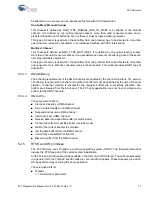
Auto Channel
This channel is defined as DMA_TYPE_AUTO. This is the pure auto channel. It is defined by a valid
producer socket, a valid consumer socket, and a predetermined amount of buffering; each of these
is a user programmable parameter.
The buffers are of equal size, the number of buffers is specified at channel creation time. Internally,
the buffers are linked cyclically by a descriptor chain.
This type of channel can be set up to transfer finite or infinite amount of data. The user application is
notified through an event callback when the specified amount of data is transferred.
Summary of Contents for EX-USB FX3
Page 8: ...8 FX3 Programmers Manual Doc 001 64707 Rev C Contents...
Page 12: ...12 FX3 Programmers Manual Doc 001 64707 Rev C Introduction...
Page 48: ...48 FX3 Programmers Manual Doc 001 64707 Rev C FX3 Overview...
Page 74: ...74 FX3 Programmers Manual Doc 001 64707 Rev C FX3 Firmware...
Page 76: ...76 FX3 Programmers Manual Doc 001 64707 Rev C FX3 APIs...
Page 84: ...84 FX3 Programmers Manual Doc 001 64707 Rev C FX3 Application Examples...
Page 98: ...98 FX3 Programmers Manual Doc 001 64707 Rev C FX3 Application Structure...
Page 148: ...148 FX3 Programmers Manual Doc 001 64707 Rev C FX3 P Port Register Access...
Page 165: ...FX3 Programmers Manual Doc 001 64707 Rev C 165 FX3 Development Tools Click next...
Page 178: ...178 FX3 Programmers Manual Doc 001 64707 Rev C FX3 Development Tools Click on Apply...
Page 180: ...180 FX3 Programmers Manual Doc 001 64707 Rev C FX3 Development Tools d Start the GDB server...
Page 185: ...FX3 Programmers Manual Doc 001 64707 Rev C 185 FX3 Development Tools...
Page 186: ...186 FX3 Programmers Manual Doc 001 64707 Rev C FX3 Development Tools...
Page 187: ...FX3 Programmers Manual Doc 001 64707 Rev C 187 FX3 Development Tools...
Page 188: ...188 FX3 Programmers Manual Doc 001 64707 Rev C FX3 Development Tools...
Page 192: ...192 FX3 Programmers Manual Doc 001 64707 Rev C GPIF II Designer...

