background image


Model TP-700


TP-700 Instruction Manual 

                                Rev. 4.1 

Page 27 of 42 

4.


RS-485 Modbus™ Protocol 

 
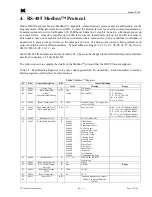
Model DM-700 sensors feature Modbus™ compatible communications protocol and are addressable via the 
program mode.  Other protocols are available.  Contact the Detcon factory for specific protocol requirements.  
Communication is two wire, half duplex 485, 9600 baud, 8 data bits, 1 stop bit, no parity, with the sensor set up 
as a slave device.  A master controller up to 4000 feet away can theoretically poll up to 256 different sensors.  
This number may not be realistic in harsh environments where noise and/or wiring conditions would make it 
impractical to place so many devices on the same pair of wires.  If a multi-point system is being utilized, each 
sensor should be set for a different address.  Typical address settings are: 01, 02, 03, 04, 05, 06, 07, 08, 09, 0A, 
0B, 0C, 0D, 0E, 0F, 10, 11…etc. 
 
Sensor RS-485 ID numbers are factory default to 01.  These can be changed in the field via the Operator Interface 
described in Section 3.5.5 Set Serial ID. 
 
The following section explains the details of the Modbus™ protocol that the DM-700 sensor supports.   
 
Code 03 - Read Holding Registers is the only code supported by the transmitter.  Each transmitter contains 6 
holding registers which reflect its current status. 
 

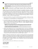
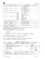
Table 3 

Modbus™ Registers


FC 

REG 

Content Description 

R/W 

Content Definition 


Value 

Meaning 

Range 

03 

40000 

Device Type 

700 Sensor 


03 
06 

40001 
40001 

Read Detectable 

Range

1,2 

Write Detectable Range 

R/W 

100 
10000 

For 0-100 
For 0-10000

2


DM – 0 to 10000 
FP – Read only 
TP – 20, 50, 100, 200 
IR – 0 to 10000 
PI – 0 to 10000 

03 

40002 


Read Concentration

3,2


1000 

Bound by range.  If > range, this 
value is in fault. 


03 
06 

40003   
40003                 

Read AutoSpan Level

4,2


Write AutoSpan Level 

R/W 

50 

Span gas at 50 

DM – 1% to 95% of Range (40001) 
FP – 5% to 95% of Range (40001) 
TP – 2% to 50% of Range (40001) 
IR – 5% to 95% of Range (40001) 
PI – 1% to 95% of Range (40001) 

03 

40004 

Read Sensor Life 

85 

For 85% sensor life 


03 

40005 

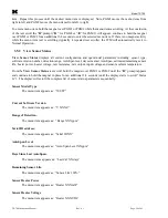
Read Fault Status Bits

5


0x0001 
0x0002 
0x0004 
0x0008 
0x0010 
0x0020 
0x0040 
0x0080 
0x0100 
0x0200 
0x0400 
0x0800 
0x1000 
0x2000 
0x4000 
0x8000 

Global Fault 
Auto Span Fault 
Temperature Fault 
4-20mA Fault 
Input Voltage Fault 
Memory Fault 
Processor Fault 
Clearing Fault 
Stability Fault 
Range Fault 
Sensor Fault 
Zero Fault 
Sensor Fault 2 
<reserved> 
In Calibration 
Communication Error 


03 

40006 

Read Model # 

1, 2, 3, 4, 5 

DM, FP, IR, TP, PID 
respectively 


03 

40007 

Read Days Since Cal 

29 

29days 


03 

40008 

4-20 Current Output 

mA x100 

400 

4.00mA 

Range 

03 

40009 

Read Input Voltage 

V x100 

2400 

24.00V 


03 

40010 

Read Temperature 

28 

28 °C 


03/

06 

40011 

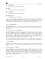
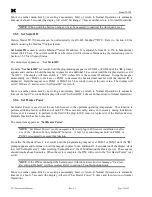
Special #1 

R/W 


Function dependent on value of 

40006 (See Special Register 

Table 4) 


Summary of Contents for TP-700

Page 1: ...rogen Sulfide Sensor This manual covers the following ranges 0 20ppm 0 50ppm 0 100ppm and 0 200ppm DETCON Inc 4055 Technology Forest Blvd The Woodlands Texas 77381 Ph 281 367 4100 Fax 281 298 2868 www detcon com June 05 2018 Document 3150 Revision 4 1 ...

Page 2: ...Model TP 700 Model TP 700 ii This page left intentionally blank ...

Page 3: ... 2 View Sensor Status 20 3 5 3 Set AutoSpan Level 21 3 5 4 Set Range 21 3 5 5 Set Serial ID 22 3 5 6 Set Heater Power 22 3 5 7 Signal Output Check 23 3 5 8 Restore Factory Defaults 23 3 6 Program Features 24 3 6 1 Operational Features 24 3 6 2 Fault Diagnostic Failsafe Features 24 4 RS 485 Modbus Protocol 27 Content Description 27 5 Service and Maintenance 29 5 1 Calibration Frequency 29 5 2 Visua...

Page 4: ...m Junction Box 8 Figure 9 Outline and Mounting Dimensions Mini Stainless Steel Junction Box 9 Figure 10 Typical Installation 10 Figure 11 Sensor Wire Connections 11 Figure 12 Magnetic Programming Tool 14 Figure 13 Magnetic Programming Switches 14 Figure 14 TP 700 Software Flowchart 16 Figure 15 Sensor Assembly 29 Figure 16 Sensor PCB 32 List of Tables Table 1 Cross Interference Gases 6 Table 2 Wir...

Page 5: ...sponse to hydrogen sulfide gas Range of sensitivity is from parts per billion to percent by volume The rugged sensor is capable of maintaining its operating characteristics for periods of up to 7 10 years in most industrial environments and as such is supported by a 10 year conditional warranty Principle of Operation Method of detection is by diffusion adsorption Air and H2S diffuse through a sint...

Page 6: ...TP 700 Sensor Assembly is completely modular and is made up of four parts See Figure 3 for Assembly Break away 1 TP 700 Intelligent Sensor Module ITM 2 Field Replaceable Plug in H2S Gas Sensor 3 Model 700 Housing Bottom Assembly contains the Housing Bottom Flame Arrestor Retaining Ring and rubber O Ring s 4 Splash Guard NOTE All metal components are constructed from electro polished 316 Stainless ...

Page 7: ...hGuard MODEL TP 700 detcon inc H 2 S Sensor Figure 3 Sensor Assembly Breakaway 1 4 Plug in Replaceable Sensor The Detcon solid state H2S gas sensor is a field proven plug in replaceable type sensor with over sized gold plated connections that eliminate corrosion problems It can be accessed and replaced in the field very easily by releasing the locking screw and unthreading the housing bottom The D...

Page 8: ...ew M3 5 x 0 6 6g6h Stainless Steel Allen set screw cup point with yield strength of greater than 40 000 PSI typical 80 000 PSI should then be tightened down to keep the Housing Bottom from being inadvertently removed or from becoming loose under vibration The locking setscrew ensures that Housing Bottom is only removable by authorized personnel with the use of special tools A M1 5 Allen Wrench is ...

Page 9: ...h experience in similar processes Ventilation Normal ventilation or prevailing wind conditions can dictate efficient location of gas sensors in a manner where the migration of gas clouds is quickly detected Personnel Exposure The undetected migration of gas clouds should not be allowed to approach concentrated personnel areas such as control rooms maintenance or warehouse buildings A more general ...

Page 10: ...and Acid liquids and concentrated vapors Heavy metals such as tetraethyl lead The presence of such contaminants in an area does not preclude the use of this H2S sensor technology although it is likely that the sensor lifetime will be shorter as a result Use of this sensor in these environments may require more frequent calibration checks to ensure safe system performance Solid State H2S sensors re...

Page 11: ...o provide a solid electrical ground path If Teflon Tape is used the Sensor must be externally grounded using a ground strap The TP 700 should be vertically oriented so that the sensor points straight downward The explosion proof enclosure or junction box would then typically be mounted on a wall or pole Detcon provides a standard selection of junction boxes available as sensor accessories See Figu...

Page 12: ...8 32 Thread Ground Point MODEL TP 700 detcon inc H2S Sensor Figure 7 Outline and Mounting Dimensions Stainless Steel Junction Box 4 3 4 NPT Explosion Proof Enclosure Junction Box Sensor Assembly Splash Guard Detcon s Aluminum Junction Box shown 2 125 5 5 13 05 Typ Mounting Bolt Use Spacers to move the J Box and Sensor Assembly away from the wall at least 0 25 0 5 to allow access to Sensor Wall or ...

Page 13: ...fications and are ATEX Approved for Class I Zone 1 Group IIB H2 area classifications Proper electrical installation of the gas sensor is critical for conformance to Electrical Codes and to avoid damage due to water leakage Refer to Figure 10 and Figure 11 for proper electrical installation NOTE If a conduit run exits the secondary port repeat the installation technique shown in Figure 10 In Figure...

Page 14: ...EYD2 or equivalent are suitable for this purpose NOTE The Detcon Warranty does not cover water damage resulting from water leaking into the enclosure through the conduit connections However since the electronics are 100 epoxy encapsulated only the wire terminations could get wet Moisture could cause abnormal operation and possibly corrosion to the terminal connections but permanent damage to the s...

Page 15: ...s NOTE 3 The supply of power should be from an isolated source with over current protection as stipulated in table Terminal Connections CAUTION Do not apply System power to the sensor until all wiring is properly terminated Refer to Section 2 7 Initial Start Up CAUTION Do not apply power to the sensor assembly in a hazardous area unless the junction box cover is tight and all electrical seals have...

Page 16: ...ensor Housing is not mechanically grounded an external ground strap must be used to ensure that the sensor is electrically grounded 2 7 Initial Start Up CAUTION Do not apply power to the sensor assembly in a hazardous area unless the junction box cover is tight and all electrical seals have been installed Upon completion of all mechanical mounting and termination of all field wiring apply system p...

Page 17: ...s mixtures This will cause significant reading inaccuracies a Connect the In Line Humidifying Tube between the cal gas cylinder and the sensor The humidifying tube will introduce the ambient relative humidity into the Cal Gas as it passes through the tube b Attach the calibration adapter to the threaded sensor housing Apply the test gas at a controlled flow rate of 200 500cc min 200cc min is the r...

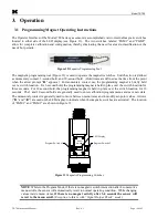
Page 18: ...n For 3 second hold the programming magnet is held in place over the switch location for three seconds For 10 second hold the programming magnet is held in place over the switch location for 10 seconds The 3 and 10 second holds are generally used to enter calibration program menus and save new data The momentary contact is generally used to move between menu items and to modify set point values Ar...

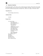
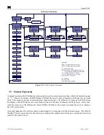
Page 19: ...s as indicated below Refer to the complete Software Flow Chart Normal Operation Current Reading and Fault Status Calibration Mode AutoSpan Program Mode View Sensor Status Sensor Model Type Current Software Version Range of Detection Serial ID address AutoSpan Level Days Since Last AutoSpan Remaining Sensor Life Sensor Heater Power Sensor Heater Voltage Raw Sensor Resistance mA Output Input Voltage...

Page 20: ...ulation PGM1 2 3 Auto Time Out Restore Defaults Auto Time Out Auto Time Out Auto Time Out Signal Output Check inc PGM1 2 3 PGM1 S PGM2 S PGM1 2 3 PGM1 2 M Set Range dec inc PGM2 S PGM1 2 3 PGM1 S dec PGM1 2 3 PGM1 2 M Set Serial ID Figure 14 TP 700 Software Flowchart 3 3 Normal Operation In normal operation the ITM Display continuously shows the current sensor reading which will normally appear as...

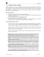
Page 21: ... N 943 000GMI CAP Remove the Detcon Splashguard and connect the adapter cover firmly in place Attach the ampoule breaking cup firmly to the cover with ampoule installed and follow the balance of the instructions for breaking ampoule and executing AutoSpan The TP 700 sensor may also be calibrated using a certified H2S gas generator product set for the correct H2S gas level and flow rate NOTE 1 Befo...

Page 22: ...roll PGM1 Exit PGM2 Span Hold the programming magnet over PGM2 for 3 seconds to execute AutoSpan or allow to timeout in 5 seconds if AutoSpan is not intended The ITM will then scroll Apply XX ppm Gas NOTE Upon entering Calibration Mode the 4 20mA signal drops to 2mA and is held at this level until the program returns to normal operation Modbus Status Register bit 14 is also set to signify when the...

Page 23: ...ll be displayed alternately with the sensor s current reading The 4 20mA output will be taken to 0mA and the Clearing Fault fault bit will be set on the Modbus output NOTE 4 The most common cause of Range Fault and Stability Fault is the improper storage of the unit sensor cell When the sensor power is removed for any period of time the sensor cell should be protected with a Desiccant Pack P N 960...

Page 24: ...tection range AutoSpan level days since last AutoSpan estimated remaining sensor life heater power heater voltage raw resistance mA output input voltage and sensor ambient temperature From the View Sensor Status text scroll hold the magnet over PGM1 or PGM2 until the prompt appears and continue to hold the magnet in place for an additional 3 4 seconds until the display starts to scroll Status Is T...

Page 25: ...t Level The display will switch to XX where XX is the current gas level Swipe the magnet momentarily over PGM2 to increase or PGM1 to decrease the AutoSpan Level until the correct level is displayed When the correct level is achieved hold the magnet over PGM1 or PGM2 for 3 4 seconds to accept the new value The display will scroll Level Saved and revert to Set AutoSpan Level text scroll Move to ano...

Page 26: ...hold or return to Normal Operation via automatic timeout of about 15 seconds the display will scroll Set Serial ID 5 times and then return to Normal Operation 3 5 6 Set Heater Power Set Heater Power is used to set the each H2S sensor to the optimum operating temperature This function is performed during factory calibration of each TP 700 sensor assembly and is not necessary during installation How...

Page 27: ...e is applied to the Modbus output gas reading NOTE Signal Output Check stays active indefinitely until the user stops the function There is no automatic timeout for this feature To end simulation mode hold magnet over PGM1 or PGM2 for 3 seconds The display will either move to the prior menu item or move to the next menu item respectively Move to another menu item by executing a momentary hold or r...

Page 28: ...mA output during this time In Calibration Status When the sensor is engaged in AutoSpan calibration the 4 20mA output signal is taken to 2 0mA and the in calibration Modbus Status Register bit 14 is set This alerts the user that the ITM is not in an active measurement mode This feature also allows the user to log the AutoSpan events via their master control system Sensor Life Sensor Life is calcul...

Page 29: ...pan calibration is performed Clearing Fault AutoSpan If the sensor fails the signal stability criteria during AutoSpan sequence Section 3 4 the Clearing Fault will be declared A Clearing Fault will cause a Fault Detected message to scroll once a minute on the ITM display and drop the mA output to 0mA The Modbus fault register bit for Clearing Fault will be set and will not clear until the fault co...

Page 30: ...on the Transient Protection Module to ensure proper sensor operation Input Voltage Fault If the detector is currently receiving an input voltage that is outside of the 11 5 28VDC range an Input Voltage Fault is declared An Input Voltage Fault will cause the Fault Detected message to scroll once a minute on the ITM display The fault register bit for Input Voltage Fault will be set and will not clea...

Page 31: ...g registers which reflect its current status Table 3 Modbus Registers FC REG Content Description R W Content Definition Value Meaning Range 03 40000 Device Type R 8 700 Sensor 03 06 40001 40001 Read Detectable Range1 2 Write Detectable Range R W 100 10000 For 0 100 For 0 100002 DM 0 to 10000 FP Read only TP 20 50 100 200 IR 0 to 10000 PI 0 to 10000 03 40002 Read Concentration3 2 R 1000 Bound by ra...

Page 32: ... 2 4 Span Gas must be less than or equal to Detectable Range and is usually about of it 5 Fault status bits self reset when fault clears 6 Text in ASCII in order L byte H byte L byte See field descriptions of notation string Gas Units String Character 1 2 3 4 5 6 7 8 9 10 11 Description Units 0x20 Gas Type 0x00 Units This field is PPM PPB or _ _ where _ is a space 0x20 0x20 The units filed is term...

Page 33: ...ction Box The moisture condensation prevention packet will prevent the internal volume of the J Box from condensing and accumulating moisture due to day night humidity changes This packet provides a critical function and should be replaced annually Detcon s PN is 960 202200 000 NOTE A desiccant cap with a desiccant packet is attached to the sensor cell housing to avoid damage during storage and sh...

Page 34: ... Thread the Bottom Housing onto the ITM to a snug fit and tighten the locking setscrew using the 1 16 Allen wrench Reinstall the splashguard f Perform Set Heater Power Section 3 5 6 to match the new sensor with the ITM g Perform a successful AutoSpan to match the new sensor with the ITM Section 3 4 5 5 Replacement of ITM Caution Hazardous areas must be declassified before opening the junction box ...

Page 35: ...ard Unthread and remove the Bottom Housing from the ITM e Feed the new TP 700 sensor assembly wires through the female NPT mounting hole and thread the assembly into the J box until tight and the ITM lens faces toward the front access point Connect the sensor assembly wires inside J Box Refer to Section 2 6 and Figure 10 f TP 700 sensors are factory calibrated however they require an initial AutoS...

Page 36: ...ng range should be 10 100 k ohms For sensors with an X in the serial number the normal reading range should be 75 k ohms to 2 meg ohms Failure would be open circuit Replace the plug in H2S sensor cell if an open circuit found AutoSpan Calibration Faults Range Stability and Clearing To clear any AutoSpan Calibration fault the AutoSpan process must be completed successfully Section3 4 Range Fault Pr...

Page 37: ...ck validity of span gas using H2S pull tube or other means check MFG date on cal cylinder Check for obstructions through stainless steel flame arrestor including being wet blocked or corroded Perform Heater Power Setting Replace the plug in H2S sensor Poor Calibration Repeatability Probable Causes Failed Sensor use of wrong Cal Gas or problems w cal gas and delivery or Interference Gases Check for...

Page 38: ...at wiring is properly connected at terminal blocks and through to controller inputs The 4 20mA output loop must be closed to avoid a Loop Fault If the 4 20mA output is not being used the green wire from the sensor must be connected to the terminal on the Transient Protection Module to ensure that it does not create a 4 20mA Fault section 2 6 Field Wiring Perform a Signal Output Check sequence via ...

Page 39: ...in section 8 TP 700 Sensor Warranty Detcon Inc will repair or replace without charge any such equipment found to be defective during the warranty period Full determination of the nature of and responsibility for defective or damaged equipment will be made by Detcon Inc personnel Defective or damaged equipment must be shipped to the Detcon Inc factory or representative from which the original shipm...

Page 40: ...uring periods of removed power or storage The sensor cell must be protected during periods of removed power or storage by use of a Dust Cap P N 602 003306 0TP and a Desiccant Packet P N 960 240010 000 Terms Conditions The original serial number must be legible on each sensor element base Shipping point is FOB the Detcon factory Net payment is due within 30 days of invoice Detcon Inc reserves the r...

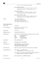
Page 41: ...Class I Division 1 Groups B C D Tamb 40 to 75 C Class I Zone I Group IIB H2 ATEX Ex d IIB H2 T4 Gb Tamb 40 tp 75 C EN60079 0 2012 EN60079 1 2007 EN50270 2006 Ingress Protection NEMA 4X IP66 Safety Approvals cCSAus Complies with ISA92 0 01 Part 1 1998 Performance Requirements for H2S CE Marking SIL2 FMEDA Rating Warranty Sensor 10 year conditional Transmitter 2 years Environmental Specifications Op...

Page 42: ...onsumption Normal operation 68mA 1 7 watt Maximum 85mA 2 watts Inrush current 1 0A 24V RFI EMI Protection Complies with EN50270 2006 Analog Output Linear 4 20mA DC current 1000 ohms maximum loop load 24VDC 0mA All Fault Diagnostics 2mA In Calibration 4 20mA 0 100 full scale 22mA Over range condition Serial Output RS 485 Modbus RTU Baud Rate 9600 BPS 9600 N 8 1 Half Duplex Status Indicators 4 digit...

Page 43: ...ming Magnet 960 202200 000 Condensation Prevention Packet for J Box replace annually 960 240010 000 Desiccant Protection Packet for Cell Calibration Accessories 943 000000 000 Calibration Wind Guard 985 241100 321 In Line Humidifying Tube 943 000006 132 Threaded Calibration Adapter 943 020000 000 Span Gas Kit Includes calibration adapter In Line Humidifying Tube 200cc min fixed flow regulator and ...

Page 44: ...ated ATEX approvals label updated EN standards that sensor assembly meets Updated ATEX listing in Specifications BM 2 9 04 02 2013 Updated ATEX installation instructions regarding use of ring terminal for earth ground using screw and lock washer Updated guidelines for metric special fasteners used in 700 assembly BM 3 0 10 25 13 Updated for 4 20mA errors LU 3 1 11 20 13 Correct Modbus Register Map...

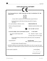
Page 45: ...d IIB H2 T4 Gb Production Quality Assurance Notification Number 01 220 103018 Issued by the Notified Body 0035 TUV Rheinland Industrie Service GMBH Am Grauen Stein D 51105 Cologne II The European Directive EMC 2014 30 UE dated from 26 02 14 Electromagnetic Compatibility Applied Standard EN 50270 2006 EMC apparatus for the detection of gases III Non Harmonized Standard Information EN 60079 0 2009 h...

Page 46: ...2 of 42 Shipping Address 4055 Technology Forest Blvd The Woodlands Texas 77381 Mailing Address P O Box 8067 The Woodlands Texas 77387 8067 Phone 888 367 4286 281 367 4100 Fax 281 292 2860 www detcon com sales detcon com This page left intentionally blank ...

Reviews: