background image

3-12

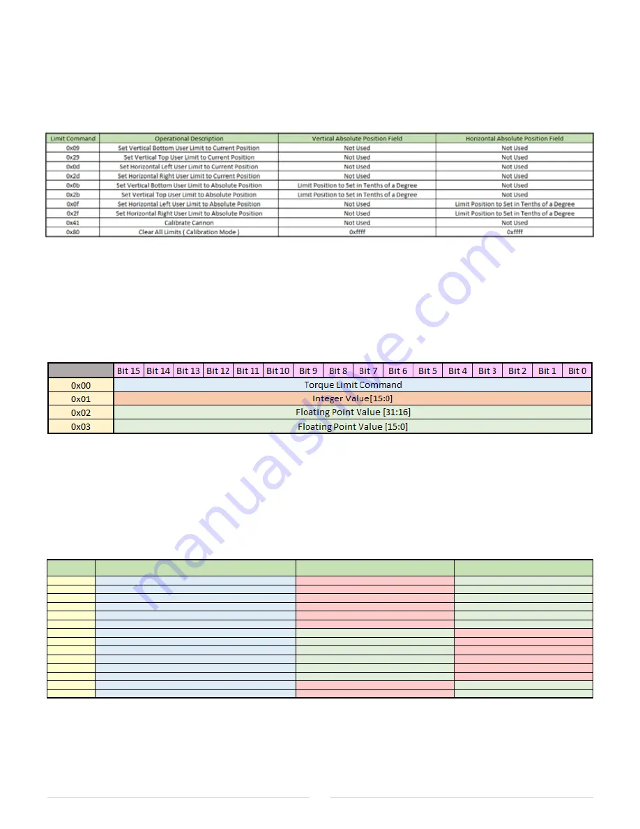
Limit Command Field is filled with the value that corresponds to the limit or operation that is 

to be executed, along with the Vertical or Horizontal Absolute Position to be Set Field if needed, 

and then issue the appropriate CIP command from the PLC. CIP Setup is similar to the Move 

Command, except that the attribute field is set to 0xc0ff and the source element field points to 

the above Limit Command Buffer. The following is a list of commands that can be executed.


Figure 3-4.1.2 Limit Commands

3-5.1 TORQUE LIMIT COMMANDS

Torque Limit Commands are used to set operational safety limits and calibration commands 

to the cannon. There are separate torque limits for the horizontal, vertical up and vertical down 

movements, along with limits for vertical and horizontal detection of movement stoppage. The 

structure of the PLC buffer for the Torque Limit Commands is as follows.


Figure 3-5.1.1 PLC Torque Limit Command Buffer

Torque Limit Command Field is filled with the value that corresponds to the operation that 

is to be executed, along with either the 16 bit integer value or the 32 bits IEEE 754 floating 

point value, and then issue the appropriate CIP command from the PLC. CIP Setup is similar 

to the Move Command, except that the attribute field is set to 0xb3ff and the source element 

field points to the above Torque Limit Command Buffer. The following is a list of Torque Limit 

Commands that can be executed.


Torque Limit 

Command

Operational Description

Integer Value Field

Floating Point Value Field

0x01

Set Vertical Up Minimum Torque ( Slow Speed Base )

Not Used

Vertical Up Minimum Torque Value

0x02

Set Vertical Up Torque Slope ( Slow to Fast Speed Mulitplier )

Not Used

Vertical Up Torque Slope

0x03

Set Vertical Down Minimum Torque ( Slow Speed Base )

Not Used

Vertical Down Minimum Torque Value

0x04

Set Vertical Up Torque Slope ( Slow to Fast Speed Mulitplier )

Not Used

Vertical Down Torque Slope

0x05

Set Horizontal Minimum Torque ( Slow Speed Base )

Not Used

Horizontal Minimum Torque Value

0x06

Set Horizontal Torque Slope ( Slow to Fast Speed Mulitplier )

Not Used

Horizontal Torque Slope

0x07

Vertical Non Movement Minimum Speed

Minimum Average Vertical Movement Speed

Not Used

0x08

Horizontal Non Movement Minimum Speed

Minimum Average Horizontal Movement Speed

Not Used

0x09

Vertical Movement Speed Margin

Vertical Speed Margin

Not Used

0x0a

Horizontal Movement Speed Margin

Horizontal Speed Margin

Not Used

0x0b

Minimum Vertical PWM for Lowest Speed Operation

Minimum Vertical PWM

Not Used

0x0c

Minimum Horizontal PWM for Lowest Speed Operation

Minimum Horizontal PWM

Not Used

0x0d

Vertical PWM Slope

Not Used

Vertical PWM Slope

0x0e

Horizontal PWM Slope

Not Used

Horizontal PWM Slope


Figure 3-5.1.2 Torque Limit Commands

Summary of Contents for HydroBlast 7100MG EXM2

Page 1: ...98613000 REV Rel HydroBlast 7100MG EXM2 Water Cannon Installation Operating Maintenance Instructions 1 574 295 8330 www elkhartbrass com...

Page 2: ...LS REQUIRED 2 1 2 3 INSTALLATION OVERVIEW 2 2 2 4 INSTALLATION STEP 1 MOUNT MONITOR 2 2 2 5 INSTALLATION STEP 2 MOUNT GATEWAY 2 2 2 6 INSTALLATION STEP 3 WIRE SYSTEM COMPONENTS 2 3 2 7 INSTALLATION ST...

Page 3: ...e nozzle 1 3 Figure 1 4 HydroBlast CAN to Ethernet IP gateway 1 4 Figure 1 5 Protective Cage 1 4 Figure 2 1 Gateway Enclosure Dimensions 2 2 Figure 2 2 Gateway Enclosure Connections 2 3 Figure 3 2 1 C...

Page 4: ...shdown system and may not have the opportunity to visit the sites where the product is installed or intended to be installed It is the responsibility of the professional installer described above to p...

Page 5: ...PA National Fire Protection Association A Ampere V Volts AC Alternating Current VAC Volts AC AWG American Wire Gauge VDC Volts DC cm Centimeters DC Direct Current ft Feet GPM Gallons Per Minute LPM Li...

Page 6: ...ould be operated from a remote location Do not needlessly expose personnel to dangerous fire conditions Open water valves supplying this equipment slowly so that piping fills slowly thus preventing po...

Page 7: ...SCRIPTION The HydroBlast washdown system is an automatic remote controllable industrial washdown monitor cannon system which performs wash operations with high flow pressurized water based on customer...

Page 8: ...can be controlled by hardwired input devices via CAN bus The monitor may be powered with 12 24VDC High power permanent magnet variable speed DC gear motors that drive the horizontal and vertical motio...

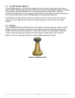
Page 9: ...ion The CCM also provides electrical power connection points for input power to the motors Electronics in the CCM enclosure are fully potted with epoxy to prevent dust and water contact 1 6 NOZZLE The...

Page 10: ...ctLogix SLC5 05 MicroLogix and other PLC controls HMI and other devices supporting Ethernet IP CIP ModbusTCP messaging and connections Figure 1 4 shows the HydroBlast CAN to Ethernet IP gateway Figure...

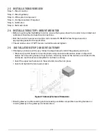
Page 11: ...cessary materials and tools 2 2 1 STANDARD SYSTEM CONTENT Monitor with onboard control module motor and harnesses Nozzle Gateway 2 2 2 ADDITIONAL ITEMS The additional items below are available separat...

Page 12: ...e onto 2 5 NPT monitor outlet thread and tighten 2 5 INSTALLATION STEP 2 MOUNT GATEWAY If Gateway enclosure will be use follow the steps below to install the gateway enclosure Mark and pre drill holes...

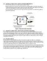
Page 13: ...ready for Normal Operation The HydroBlast cannon is typically pre calibrated from the factory and will default the user programmable limits to the maximum safe operation of the cannon only limited by...

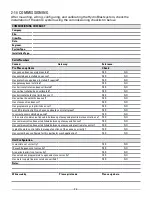
Page 14: ...S NO Has stow position been set YES NO Has programming stop limits been set YES NO Are LED indication lights on Cannon onboard control all green YES NO Is correct power cable being used YES NO Is the...

Page 15: ...unts Top Mechanical Limit 135 45 Pointing Up Figure 3 2 1 Cannon Horizontal Coordinate System Figure 3 2 2 Cannon Vertical Coordinate System The cannon position status is reported in tenths of a degre...

Page 16: ...ibility that when the cannon is commanded to go to the 45 degree mark it will travel into the lower vertical mechanical stop at around the 48 degree mark If this occurs reset the monitor to its calibr...

Page 17: ...urred If the reason that the Jog command ended was due to hitting a limit a Command Error bit is also set All status bits are cleared upon executing a new command 3 3 3 GOTO MODE In Goto Mode you can...

Page 18: ...and is shown here below This buffer is designed to be sent to the gateway where it will be converted into an 8 byte CAN message and sent to the cannon Note that PLC Big Endian 16 bit integers are tran...

Page 19: ...uration whenever you set a jog bit to true then the cannon will start to move at the programmed speed If you modify the horizontal speed field then the move will change speed dynamically This mode is...

Page 20: ...r vertical axis the Command in Process bit will be set In the case where the command would result in no movement for example setting all the Jog bits to zero the Command in Process will be cleared and...

Page 21: ...al move the appropriate distance and speed is calculated to make the horizontal and vertical portions of the moves to complete at the same time Hitting a user or hard limit will stop the movement for...

Page 22: ...s set to 0xb3ff and the source element field points to the aboveTorque Limit Command Buffer The following is a list ofTorque Limit Commands that can be executed TorqueLimit Command Operational Descrip...
Page 23: ...the desired speed of 0 5 degrees second is meet Now repeat these same jog commands but with the maximum speed 15 degrees second programmed into the Jog commands Slowly increase the PWM slope from 0 i...

Page 24: ...LED Indication State Interpretation Power LED ON Cannon is powered Horizontal LED ON Cannon received command from remote control or joystick control to move left or right Vertical LED ON Cannon recei...

Page 25: ...ing nozzle flow test inspect monitor swivel joints for leaks Inspect all exposed wiring for signs of damage If protective cage is used use the appropriate tool to clean the cage of dust build up Note...

Page 26: ...low provides descriptions and part numbers available for the HydroBlast wash system Part Number Description 00007100MG HydroBlast Wash System including brass monitor with DN80 flange onboard control b...

Page 27: ...current 5A Stall current 10A Current trip point 8A Material Silicon Bronze Flange DN80 Table E per AS2129 2 5 inlet ID Seals Industrial grade bearing seals Weight 63 LBS Operating temperature range 4...

Page 28: ...5 2 5 5 NOTES...

Page 29: ...5 3...

Page 30: ...5 4...

Page 31: ...5 5...

Page 32: ...khart Brass Manufacturing Co Inc 1302 W Beardsley Avenue Elkhart IN 46514 Tel 574 295 8330 Toll Free 800 346 0250 Fax 574 293 9914 www elkhartbrass com Email eb info safefleet net 98613000 REV Rel 11...

Reviews: