ESR Series Routers Operation Manual
37
7
ROUTER CONFIGURATION EXAMPLES
7.1
VLAN Configuration
VLAN (Virtual Local Area Network) is a logical (virtual) local area network that represents a group of
devices which communicate on channel level regardless of their physical location.
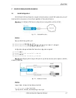
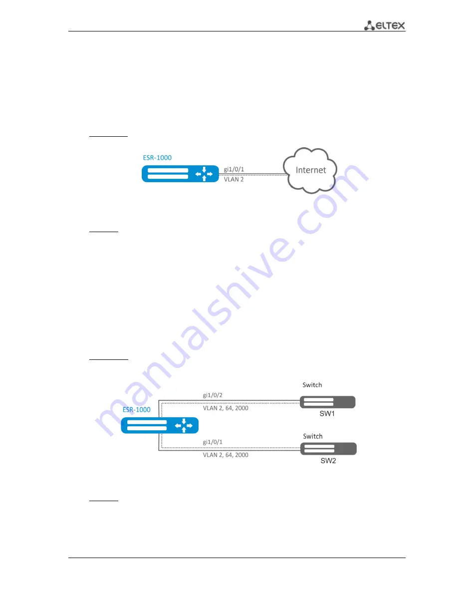
Objective 1:
On the basis of the factory configuration, remove gi1/0/1 port from VLAN 2.
Fig. 7.1
—
Network structure
Solution:
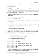
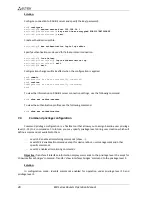
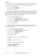
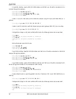
Remove VLAN2 from gi1/0/1 port:
esr-1000(config)#
interface gi 1/0/1
esr-1000(config-if-gi)#
switchport general allowed vlan remove 2 untagged
esr-1000(config-if-gi)#
no switchport general pvid
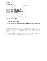
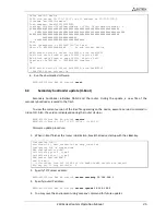
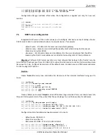
Configuration changes will take effect when the configuration is applied:
esr-1000#
commit
Configuration has been successfully committed
esr-1000#
confirm
Configuration has been successfully confirmed
Objective
2:
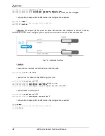
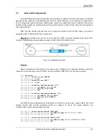
Configure gi1/0/1 and gi1/0/2 ports for packet transmission and reception in VLAN 2,
VLAN 64, VLAN 2000.
Fig. 7.2
—
Network structure
Solution:
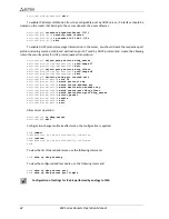
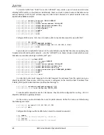
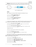
Create VLAN 2, VLAN 64, VLAN 2000 on ESR-1000:
esr-1000(config)#
vlan 2,64,2000
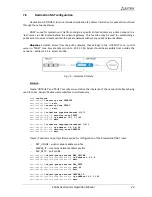
Specify VLAN 2, VLAN 64, VLAN 2000 for gi1/0/1-2 port:

