Communication System Manual
UPS System: HIPULSE E
(Modbus/Jbus Interface)
Description of Protocol
(04/07)
Page 5-5
5.4
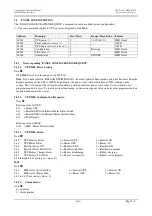
PANEL CONFIGURATION
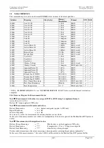
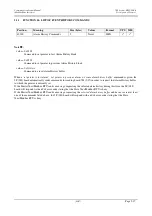
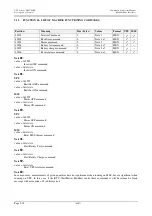
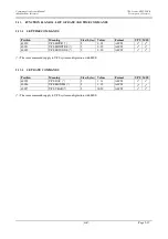
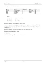
The ‘PANEL CONFIGURATION REQUEST’ command is used to read the system configuration.
(*) The same commands apply to UPS system configuration with MSS.
Address
Meaning
Size (bytes)
Range / Resolution
Format
40001
UPS power (*)
2
10:3200 kVA
HEX Note 1
40002
Panel software release (*)
4
ASCII
40004
UPS Logic software release (*) 4
ASCII
40006
Configuration
2
Rotating
HEX Note 2
40007
UPS status (*)
2
HEX Note 3
40008
Alarm status
2
ON/OFF
HEX Note 4
5.4.1
Notes regarding ‘PANEL CONFIGURATION REQUEST’
5.4.1.1
UPS\MSS Power Setting
Note
UPS\MSS Power is in the range 10 to 3200 kVA.
Note:
If you have selected ‘RELOAD UPS/MSS DATA’ from the Operator Panel menu or data has been lost from the
Eeprom memory on the UPS (or MSS) Logic Board, the power value will be initialised at 9999, locking up the
system. This is to prevent the system from functioning with an incorrect power value when it is first turned on or
programming data is reset. To restore correct functioning, set the correct power value and any other programming data
required, then restart the system.
5.4.1.2
UPS\MSS Configuration Parameter:
Note
Rotating value for UPS:
0x0
= Single UPS
0x1
= Parallel UPS with Internal Mains Static Switch
0x2
= Parallel UPS with External Mains Static Switch
0x3
= ECHO mode
Rotating value for MSS:
0x03 = MSS (Mains Static Switch)
5.4.1.3
UPS\MSS Status:
Nota
bit 0
UPS Inverter Status
0 = Inverter OFF
1 = Inverter ON
bit 1
UPS Mains Status
0 = Mains OFF
1 = Mains ON
bit 2
Rectifier Status ON
0 = Rectifier OFF
1 = Rectifier ON
bit 3
Rectifier Status MANUAL
0 = Rectifier on buffer
1 = Rectifier on manual
bit 4
UPS Battery Charger Status
0 = Battery discharging
1 = Battery charging
bit 5
UPS Battery Test Status
0 = Battery test inactive
1 = Battery test in progress
bit 6 through bit 15 not in use (value = 0)
MSS
Note
bit 0
MSS status (Inverter Side)
0 = Inverter OFF
1 = Inverter ON
bit 1
MSS status (Mains Side)
0 = Mains OFF
1 = Mains ON
bit 2 to bit 15 not in use (value = 0)
5.4.1.4
Alarm Status:
Note
0 – no alarm
1 - alarm present


