background image

10 


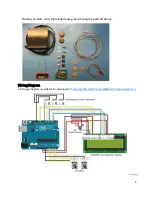
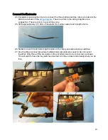
Connect the Electronics 

24. Cut appropriate lengths of wire to connect the three buttons and two rotary encoders to the 

Arduino as shown in the 

wiring diagram

. The wire colors in the wiring diagram are a 

suggestion. The wire colors in your kit may vary. 

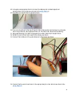
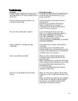
25. Strip approximately ½"/12mm of insulation from either side of each length of wire.


26. Solder one end of each wire length to pins on the rotary encoders and key switches. 
27. Use the Wago connectors where multiple black (ground) wires need to be connected 

together. Only three of the five leads on the encoders need to be connected, as shown. 
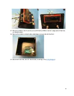
You will  want to have the key switches inserted into the enclosure lid already when you do 
this. 


Summary of Contents for LIGHTHACK BOX 1

Page 1: ...cm 4201B7005 1 Blue Wire Solid Core 22AWG 0 65mm2 2 3 60 90cm J4630 3 5 position Wago Wire Connector J4629 1 3 position Wago Wire Connector W6378 1 USB Cable A to B HW0006 10 Machine screws 2 56x3 16...

Page 2: ...2 Before you start verify that all parts are present using the parts list above WiringDiagram A full pagediagramis availablefor download at https github com ETCLabs lighthack tree master box_1...

Page 3: ...Arduino USB Test sketch lighthack master test_tools usb_test usb_test_sketch usb_test_sketch ino in the Arduino IDE 3 Before the sketch will compile we need to add additional code called a library so...

Page 4: ...e Arduino to your computer using the USB cable 7 The Arduino IDE will automatically detect your Arduino Uno and select it You can verify this in the Tools menu 8 Press the arrowto upload your sketch t...

Page 5: ...The TX and RX lights should blink in sequence once per second Press Incoming OSC and you should see repeating messages of OSC Packet eos ping and a number counting up These messages indicate that you...

Page 6: ...ut out the template and lay it over the top of the enclosure lid using the screwholes or tape to make sure it doesn t move 17 Drill out the holes using the proper size drill bits Drill starter holes i...

Page 7: ...e or rectangular file file out the square holes and slot or use your preferred method of making square holes 20 Test fit the Cherry MX Red switches into the square holes as you file to make sure you h...

Page 8: ...edges of the square holes This makes the plastic surrounding the hole thinner so that the Cherry MXRed switches can clip in properly TIP It may be helpful to trace the edges of the square holes into...

Page 9: ...d a good location to be 1 25mm in from a corner and 12mm up from the bottom Use a 12mm drill bit to drill a hole for the USB connector Make sure you can connect a USB cable to your Arduino through the...

Page 10: ...t may vary 25 Strip approximately 12mm of insulation from either side of each length of wire 26 Solder one end of each wire length to pins on the rotary encoders and key switches 27 Use the Wago conne...

Page 11: ...ubber washer and locking ring string the wire through the box then tighten with the nut This has to be done before soldering 31 Strip approximately 12mm of insulation from either side of each length o...

Page 12: ...nishthe assembly Now that your module has been tested it s time to put it in the enclosure 37 Insert the two encoders through the holes from the inside of the lid 38 Use the included panel mounting nu...

Page 13: ...enclosure such that the USB connector is aligned with the hole you drilled earlier 42 Secure the Arduino using double sided tape or your preferred method 43 Reconnect all of the wires to the Arduino...

Page 14: ...14 44 Secure the face plate to the enclosure using the four black screws TIP You may want to use some electrical tape for cable management...

Page 15: ...15 45 Press fit the keycaps and encoder finger wheels onto the key switches and encoders 46 Re test the module to make sure everything still works Congratulations You re done...

Page 16: ...REVERSE i e define PAN_DIR REVERSE Screen glitches or displays strange characters Check the screen s solder connections for cold joints Check the screen s connections to the Arduino Make sure no conn...

Page 17: ...ot connected to a compatible Eos Family device On solid L solid TX heartbeat RX off When you have loaded the USB test sketch and areconnected to a compatible Eos Family device On solid L solid TX hear...

Reviews: