11.4 Sensor not connected
The device has the ability to detect when there is no sensor connected
or when the sensor is broken and causes an open circuit.
When the device detects the sensor error, the device will:
• Set the relay to OFF
• Blink red and green from the LED
• Send a temperature report of 124°C
To clear the “Sensor not connected” error the device has to be
disconnected from the mains, and the wiring and sensor needs to be
checked. When the fault is resolved the mains can be reconnected and
the device will function normally again.
12. CALIBRATION
Parameter 6 allows you to calibrate the temperature displayed in the
controller/gateway and what the thermostat uses for regulation. If
the temperature sensor readout is not correct, you can make minor
changes to the temperature readout. You can calibrate the measured
temperature by ±6°C degrees.
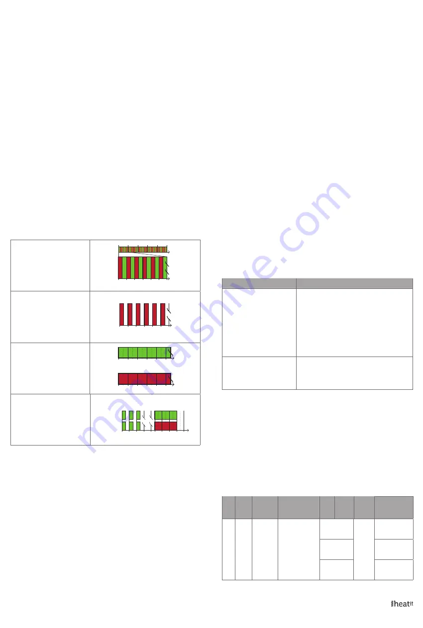
13. LED BLINKING PATTERNS DESCRIPTION
The device supports numerous LED blinking patterns to make it as
easy as possible to identify what the device is doing.
Error code
Error status on device:
Alternating red and green blinking
pattern (100ms duration) for 5
seconds.
200ms
0s
1s
2s
3s
4s
5s
400ms 800ms 1000ms
600ms 900ms
Device Not in Network
The LED will flash red when the de-
vice is not added to a Z-Wave network
0s 1s 2s 3s 4s 5s
Device Status
On: Green
Off: Red
When the device is in OFF Mode, LEDs
will be off.
Add/Remove
When device enters add/remove
mode the LED will flash green.
If successful, the LED will light up in
green for 3 seconds.
If unsuccessful, the LED will light up in
red for 3 seconds.
0s
1s
2s
3s
xs
x+3s
Success
Fail
14. QR-CODE PLACEMENT (DSK)
The QR-Code is needed when including a device using S2 security or
SmartStart. The DSK can be found in the QR-Code and is located;
• On the product.
• On the Quick Guide manual.
• On the product box.
15. SECURITY
S2 security enhances Z-Wave Plus with an additional layer of AES
128-bit encryption of the wireless Z-Wave communication to prevent
hacking and man-in-middle attacks on the home network. This device
supports S2 and has a Z-Wave DSK QR-Code label that may be used
when the module is added to the Z-Wave home network. The primary
controller will ask for a 5-digit code, which can be found underneath
0s
1s
2s
3s
4s
5s
0s
1s
2s
3s
4s
5s
the QR-Code. The primary controller will then ask you to confirm the
rest of the code that is contained in the QR-Code.
16. NODE INFORMATION FRAME
The node information frame is the ”business card” of a Z-Wave device.
It contains information about the device type and its technical features.
The add and remove procedure of the device is confirmed by sending
out a node information frame. Besides this, it may be necessary for
certain network operations to send out a node information frame.
17. ASSOCIATIONS
Z-Wave devices interact with other Z-Wave devices. The relationship
between one device controlling another device is called an association.
In order to control a subordinate device, the controlling device needs
to maintain a list of devices that will receive controlling commands.
These lists are called ”Association Groups”. They are always related to
the specific event triggered (e.g., sensor reports). In case the event is
triggered, all devices stored in the respective association group will
receive a joint wireless command.
17.1 Setting and removing associations
Associations may be assigned and removed via Z-Wave commands.
Please refer to your primary controller/Z-Wave gateway for more
information.
17.2 Association groups
RELAY DEVICE
THE MAIN DEVICE
Group 1
Lifeline
Lifeline. (Normally used by the Z-Wave Controller) Sends:
- Device Reset Notifications.
- Thermostat Setpoint Reports.
- Thermostat Mode Reports.
- Thermostat Operating State.
- Sensor Multilevel Report.
- Meter report.
- Basic report.
- Indicator report.
Max. nodes in group: 5
Group 2
External Control
Send Binary Switch set commands representing the
status of the internal relay.
(0x00, 0xFF) ON/OFF
Max. nodes in group: 5
18. CONFIGURATION PARAMETERS
Z-Wave products are supposed to work out of the box after inclusion.
Some device configuration may, however, alter the functionality to
better serve user needs or unlock further enhanced features. All the
parameters below do not feature altering capabilities, advanced or
read only flag.
Parameter 1, Parameter size 1. Operating mode.
Sets the thermostat mode.
NO
#
PARA
SIZE
(BYTE)
NAME
SHORT
DESCRIPTION /
COMMENT
MIN
MAX
DE-
FAULT
DESCRIPTION
OF VALUE
1
1
Operating
mode
Sets the thermo-
stat mode
0
1
OFF
Thermostat will
not operate
1
Heating Thermo-
stat is in heating
mode
2
Cooling
Thermostat is in
cooling mode


