HF-A11 Embedded WiFi Module User Manual
Shanghai High-Flying Electronics Technology Co., Ltd
www.hi-flying.com
17
1.4.3. Multi-TCP Link Connection
When HF-A11 module configured as TCP Server, it supports Multi-TCP link connection, and
maximum 32 TCP clients permit to connect to HF-A11 module. User can realize multi-TCP link
connection at each work mode.
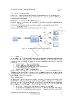
Multi-TCP link connection will work as following structure:
Upstream: All dates from different TCP connection or client will be transmitted to the serial port as
a sequence.
Downstream: All data from serial port (user) will be duplicate and broadcast to every TCP
connection or client.
Detailed multi-TCP link data transmition structure as following figure:
Figure 13. Multi-TCP Link Data Transmition Structure
1.4.4. TCPB
Function
HF-A11 support 2xTCP function, which means module can support 2 network connections at the
same time. The 2
nd
net work connection called TCPB. TCPB only works as TCP Client and its
configuration can only through AT commanrd, not Web configuration supported. The command
as following,
¾
AT+TCPB=on, Enable TCPB function;
¾
AT+TCPPTB=<port>, Set TCPB port number;
¾
AT+TCPADDB=<IP or domain>, Set TCPB’s server address;
¾
AT+TCPTOB=<time>, Set TCPB timeout;
¾
AT+TCPLKB, Query TCPB link status;
Detailed command describtion refer ro AT instruction chapter. After enable TCPB function, two
network interfaces’ work mode like “Multi-TCP Link”, All dates from each TCP connection will be
transmitted to the serial port as a sequence and all data from serial port (user) will be duplicate
and broadcast to each TCP connection.
1.4.5. GPIO
Function
HF-A11 module support 2 GPIO mode: GPIO-1 and GPIO-2. At GPIO-1 mode, UART (TXD/
RXD/CTS/RTS) defined as GPIO and others (nReady/nLink/nReload) defined as functional pin.
At GPIO-2, all these 7 pins defined as GPIO. So, GPIO mode not supports UART communication.
When module works at GPIO mode, PC and other equipts can setup connection (TCP/UDP)
through WiFi, then read/write GPIO information through command.
¾
GPIO n IN, Set GPIOn as input, Response GPIO OK or GPIO NOK;
¾
GPIO n OUT 0, Set GPIOn as output and output ‘0’, Response GPIO OK or GPIO NOK;
¾
GPIO n OUT 1, Set GPIOn as output and output ‘1’, Response GPIO OK or GPIO NOK;
High-Flying

