Example Application 5-4
© 2012 HMS Industrial Networks AB
Doc.Id. HMSI-168-25
J1939 I/O Configuration
Input Data Points
The input data points are responsible for determining where in the Input table the
J1939 data is to be placed. It is desirable to be able to address the 2 parameter val-
ues in our example as individual registers in Modbus. Since the values are packed
into 3 bytes in the J1939 message, they need to be parsed out into 2 register loca-
tions in the Input table.
Since Modbus registers are addressed as 16-bit words, each Modbus register
occupies 2 bytes in the Input table. Placing values into Modbus registers requires
that values be placed on even byte boundaries in the Input table (0, 2, 4,...).
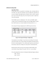
The resulting J1939 input configuration from BWConfig is shown below.
2 data points have been defined, 1 for each value in the message. The first data
point copies the first value (12 bits starting at the beginning of the message) into
the first word of the Input table. The second data point copies the second value (12
bits starting 12 bits into the message) into the second word of the Input table.
Both data points monitor the network for messages with PGN 4608 and any
source address (Target Address 255 specifies “don’t care” source address).
The resulting Input table provides the following Modbus Input Register addresses:
30001 Value #1
30002 Value #2
Figure 5-5 Example J1939 Input Configuration


