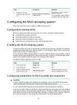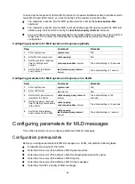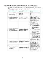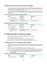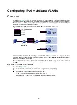
73
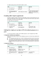
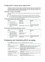
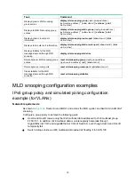
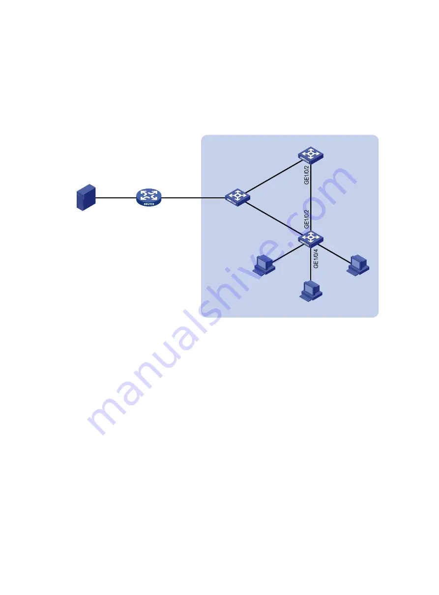
attached to Switch C only along the path of Switch A—Switch B—Switch C. When this path is
blocked, a minimum of one MLD query-response cycle must be completed before IPv6
multicast data flows to the receivers along the path of Switch A—Switch C. In this case, the
multicast delivery is interrupted during the process. For more information about the STP, see
Layer 2—LAN Switching Configuration Guide
.
Configure GigabitEthernet 1/0/3 on Switch A as a static router port. Then, IPv6 multicast data
uninterruptedly flows to the receivers along the path of Switch A—Switch C when the path of
Switch A—Switch B—Switch C is blocked.
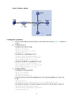
Figure 25 Network diagram
Configuration procedure
1.
Assign an IPv6 address and prefix length to each interface according to
. (Details not
shown.)
2.
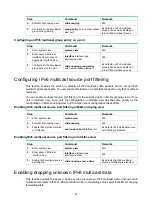
Configure Router A:
# Enable IPv6 multicast routing.
<RouterA> system-view
[RouterA] ipv6 multicast routing
[RouterA-mrib6] quit
# Enable MLD on GigabitEthernet 1/0/1.
[RouterA] interface gigabitethernet 1/0/1
[RouterA-GigabitEthernet1/0/1] mld enable
[RouterA-GigabitEthernet1/0/1] quit
# Enable IPv6 PIM-DM on GigabitEthernet 1/0/2.
[RouterA] interface gigabitethernet 1/0/2
[RouterA-GigabitEthernet1/0/2] ipv6 pim dm
[RouterA-GigabitEthernet1/0/2] quit
3.
Configure Switch A:
# Enable MLD snooping globally.
<SwitchA> system-view
[SwitchA] mld-snooping
Source
1::1/64
Router A
MLD querier
GE1/0/1
2001::1/64
Switch A
Switch B
Switch C
GE1/0/1
GE
1/0
/2
GE
1/0
/3
GE
1/0
/1
GE
1/0
/1
GE
1/0
/3
GE
1/0
/5
Host A
Receiver
Host B
Host C
Receiver
VLAN 100
GE1/0/2
1::2/64

