MiniSmart II
39
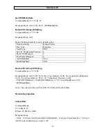
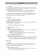
<Tag 0x00> data: 00 <Len-32> <Sha-2 Signature Data 2>
<Tag 0x02> data: 02 <Len x> <x bytes Device Name Data> (Such as 02 0E
+ “Smart PIN L100”, or 01 0C + “MiniSmart II”)
BASE1 Data needs to be equal to BASE Data
Device Examples
Example 1
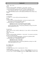
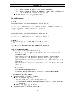
If Application Whole Size is 480K, BIN file is 396.6K, m is 1K.
The Check Value of Block 3 need be calculated from 397K data, FM Generator Tools
need padding (397K – 396.6K) bytes 0xFF to calculate it.
Example 2
If Application Whole Size is 480K, BIN file is 400K, m is 2K.
The Check Value of Block 3 need be calculated from 400K data
Example 3
If ApplicationWhole Size is 480K, BIN file is 480K, m is 1K.
The Check Value of Block 3 need be calculated from 480K data.
Entering Bootloader Mode
1.
Device enters into Bootloader Status method.
While Device runs in Application IDLE Status, Host could send Command
Commandy Body:
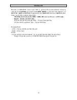
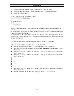
78 46 7A 49 52 46 57 00 00 00 00 00 00 00 00 – Master Chip Bootloader
78 46 7A 49 52 46 57 00 00 00 00 00 00 00 01 – Slave Chip Bootloader
78 46 7A 49 52 46 57 FF FF FF FF 00 00 00 00 – Master Chip Bootloader need
be changed
78 46 7A 49 52 46 57 FF FF FF FF 00 00 00 01 – Slave Chip Bootloader need be
changed
Response Body:
06 (Enter into Bootloader Status), or
15 (Do Not Support Bootloader, or Do Not Enter into Bootloader Status).
2.
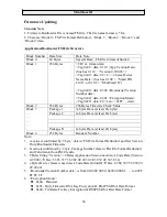
Bootloader Work Status Display:
Device with LED: LED display to indictor:
Dual-Color LED (Optional):
Without Battery Identifier: Flash Red & Green
With Battery Identifier: Flash Red (Battery is low), or Flash Green (Battery
is enough)
Multi LEDs (Optional): Flash them
Device with LCD, LCD display ‘Bootloader …’

