Programmable robot with micro:bit
33
3.1.3 Input/Output Pins
There are 25 external connectors on the edge connector of the micro:bit, which
we refer to as ‘pins’. Program motors, LEDs, or other electrical components with the
pins, or connect extra sensors to control your code!
The edge connector brings out many of the GPIO circuits of the application
processor. Some of these circuits are shared with other functions of the micro:bit, but
many of these extra circuits can be re-allocated to general purpose use if some software
features are turned off. Note: the nRF51 data sheet states that GPIO pins may be in std-
drive (0.5mA) and high-drive (5mA) mode, with a maximum of 3 pins in high-drive mode at
any one time.
Rings
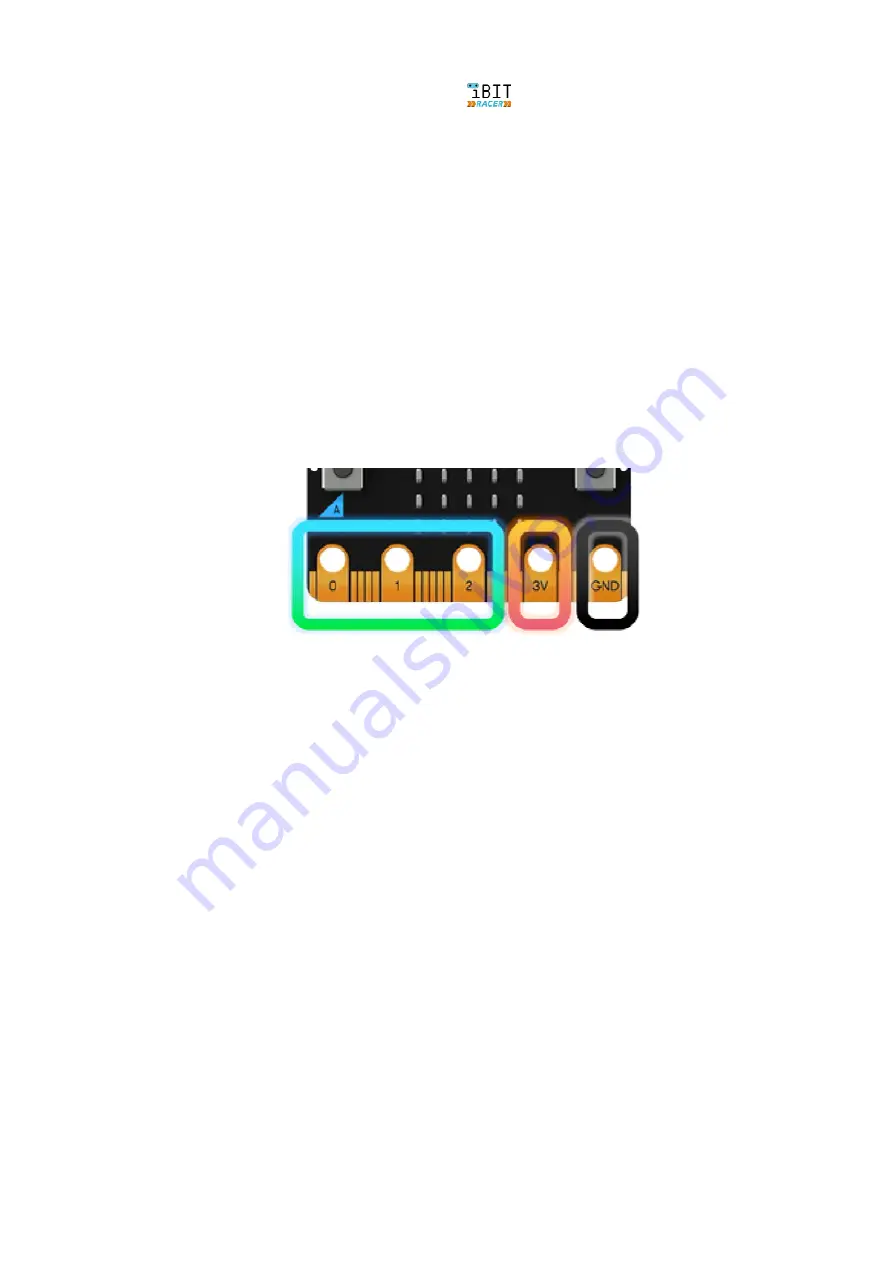
3 large IO rings and two large power rings, 4mm plug and crocodile clip compatible
GPIO features
19 assignable GPIO pins
2 are assigned to the on board I
2
C interface
6 are used for display or light sensing feature
2 are used for on board button detection
1 is reserved for an accessibility interface
19 may be assigned as digital input or digital output
19 may be assigned for up to 3 simultaneous PWM channels
19 may be assigned for 1 serial transmit and 1 serial receive channel
6 may be assigned as analog input pins with 10-bit ADC resolution (0....1023)
3 may be assigned to an optional SPI communications interface
3 may be assigned for up to 3 simultaneous touch sensing inputs
Pitch
1.27mm, 80 way double sided.
Pads
5 pads, with 4mm holes
Summary of Contents for iBIT RACER
Page 4: ...4 Programmable robot with micro bit...
Page 18: ...18 Programmable robot with micro bit...
Page 30: ...30 Programmable robot with micro bit Now the BIT Racer robot is ready for coding and fun...
Page 38: ...38 Programmable robot with micro bit...
Page 50: ......
Page 61: ...Programmable robot with micro bit 61...
Page 63: ...Programmable robot with micro bit 63...


