36
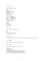
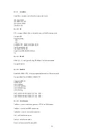
SetDefaultConfig clears all settings and then sets logging on AIN1, V3V and VPOWER. To save use SaveConfig command
11.1.14
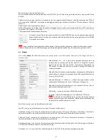
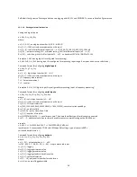
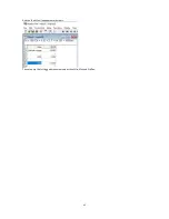
Settings via terminal session
Analog and digital inputs
a x, M=y, G=y, U=y, R=y
where:
a x [1-4 , 9-12] – analog input number (AIN1-4 …AIN9-12)
M=y [0,1] – if M=1, activate measurements on this input
G=y [1…8] – ranGe for differential inputs (a 9 … a 12) 19, 38, 78,156, 312, 625, 1250, 2500mV
U=y [0,1] – unipolar setting (U=1) or bipolar setting (U=0) for differential inputs (a 9 … a 12)
R=y [0,1] – calculating ratio to a9 for inputs a10 … a12. a x becomes100* AINx / AIN9 for Pt-100
Example a 1,M=1 (analog input 1 is configured for measuring)
a 9,M=1, G=8, U=1, R=0 (analog input 9 is configured for measuring, input range 8, unipolar and no ratio calculation)
Command format for configuring
digital inputs
:
d x, M=y, F=y, T=y, C=y
where:
d x [1…4] – digital input number (d 1 … d 4)
M=y [0,1] – if M=1, activate measurements on this input
F=1 – frequency measurement
T=1 – time measurement
C=1 – counter
Example d 5, M=1, F=1 (digital input 5 is configured for measuring, input is frequency measuring)
Command format for configuring
serial inputs
:
s x, M=y, C=y, S=y, B=y, P=y, T=y, D=z, A=z
where:
s x [1…8] – serial input number (s 1 … s 8)
M=y [0,1] – if M=1, activate measurements on this input
C=y [1, 2] – COM port selection
S=y [300, 1200, 2400, 9600, 19200, 38400, 57600, 115200] – communication speed bps
B=y [7, 8] – number of bits
P=y [N, E, O] – parity None, Even, Odd
T=y [1, 2] – number of stop bits
D=z [KIPPZONEN_SMPX…] – serial driver name. This name identifies type of serial sensor connected
A=z [1, …]] – address of serial sensor (mostly used for sensors communicating on the RS-485 bus)
example
s 5, M=1, C=1, S=19200, B=8, P=E, T=1, D=KIPPZONEN_SMPX, A=1
(serial sensor 5, connected on COM1 with 19200bps 8E1 settings; type of sensor is SMPx
series and bus address is 1)
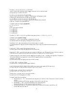
Command format for configuring
outputs
:
o x, I=y, L=y, N=y, X=y, S=y, V=y, P=y, A=z
where:
o x [1…32] – output number (o 1 … o 32)
I=z [A1…A20, D1…D8, S1…S8, I1…I14] – map to measured input
L=y [0, 1] – logging
N=y [0, 1] – logging minimum value
X=y [0, 1] – logging maximum value
S=y [0, 1] – logging standard deviation value
V=y [0, 1] – vector calculation
P=z [1 … 16] – polynomial number for calculation
A=z – alias – name of logged variable

