background image

HPO-9007 Series Gateways Installation Guide 

4 923-019-05B

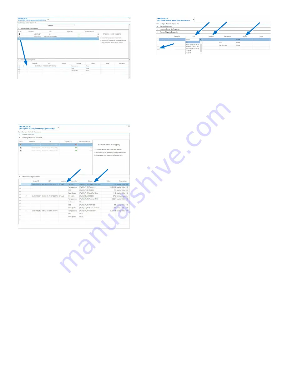
5.  Click in the Object column and select the 

relevant 

AV object(s)

 in the drop-down 

box(es).

6.  If desired, click in the Location column to add a 

description of the sensor’s location.

(Method 2) Manual Sensor/Device Addition

NOTE: 

With Method 2, configuration of 

sensors can be done before the STW/

THW sensor signals are present or 

when using other compatible EnOcean 

devices with the selectable profiles.

1.  In the Sensor Mapping Properties section, click 

the 

+

 (plus) sign in the bottom row.

2. 

Click in the Sensor ID field and enter a valid 

sensor identification number 

(from the label 

on the device).

3. 

Click in the EEP field and select the 

EnOcean 

Equipment Profile (EPP) number

 for the 

desired device from the drop-down box.

4.  Click in the Object column and select the 

relevant 

AV object(s)

 in the drop-down 

box(es).

5.  If desired, click in the Location column to add a 

description of the sensor’s location.

6.  Click 

Save Changes

.

Configure Value and Programming Objects

1. 

Configure the relevant AVs as needed from the 

above steps (e.g., add object names and units) 

and click 

Save Changes

.

NOTE: 

For temperature in degrees C or 

humidity only, you are done. Confirm 

that temperature and humidity 

readings are functioning properly.

2.  For degrees F or a setpoint, add the following 

(or equivalent) code to an unused Control 

Basic program object.

REM WIRELESS SENSOR CODE EXAMPLES

REM Use different AVs as needed

REM Configure AVs for applicable 

relinquish defaults and units

REM Convert STW/THW Degrees C to F

REM AV40 = Temp in Degrees C from 

STW/THW Sensor

REM AV1 = Temp in Degrees F 

Converted from AV40

AV1@8 = AV40 * 1.8 + 32

REM STW-6014 Setpoint Offset

REM In PRG1, add REM before the “U 

= DS1.KMC_STAT_STATUS” line

REM Sets MSV10 to STE-6014/7

MSV10@8 = 9

Summary of Contents for Conquest HPO-9007 Series

Page 1: ... into the backplate until the screw clears the cover NOTE The hex screw should remain in the backplate INTRODUCTION Complete the following steps to Mount a KMC Conquest HPO 9007NW or HPO 9007DW gateway Connect it to a KMC Conquest BAC 59xx 9xxx controller Discover wireless sensors NOTE The HPO 9007s only receive signals from sensors They do not transmit signals to devices NOTE See the data sheet a...

Page 2: ...nnect software ver 1 0 13 x or later KMC TotalControl software ver 4 5 0 x or later See the documents or Help systems for the respective KMC tools for more information If the the HPO 9007 is connected to an optional HPO 9001 NetSensor distribution module for use Hex Screw 2 Pull the cover off the backplate CONNECT ETHERNET CABLE 3 Feed the Ethernet patch cable from the Conquest controller through ...

Page 3: ...that is inside of the sensor body Add Sensors Method 1 Automated KMC Sensor Discovery NOTE For devices other than KMC STW THW sensors use Method 2 1 On the back of the sensor press the Learn button on the side or top of the button body dependent on the model with a small screwdriver 2 In Gateway Sensor List Properties wait until the fields for the sensor to populate with an icon and profile NOTE I...

Page 4: ...bject column and select the relevant AV object s in the drop down box es 5 If desired click in the Location column to add a description of the sensor s location 6 Click Save Changes Configure Value and Programming Objects 1 Configure the relevant AVs as needed from the above steps e g add object names and units and click Save Changes NOTE For temperature in degrees C or humidity only you are done ...

Page 5: ...ill be transmitted within a few minutes NOTE Momentarily pressing the Learn button sends a new identification transmission immediately but that transmission does not include sensor temperature setpoint or humidity values USE OF HPO 9001 DISTRIBUTION MODULE To use multiple HPO 9007 gateways and or STE 9000 series NetSensors on a single controller an HPO 9001 distribution module is required The HPO ...

Page 6: ...ith respect to this document In no event shall KMC Controls Inc be liable for any damages direct or incidental arising out of or related to the use of this document The KMC logo is a registered trademark of KMC Controls Inc All rights reserved TEL 574 831 5250 FAX 574 831 5252 e mail info kmccontrols com 2020 KMC Controls Inc Specifications and design subject to change without notice The sensors m...

Reviews: