background image


                     User’s Manual 

LG Programmable Logic Controller

LG Industrial Systems


G3F-AD3A 
G4F-AD3A 
G6F-AD2A 

Summary of Contents for G3F-AD3A

Page 1: ...User s Manual LG Programmable Logic Controller LG Industrial Systems G3F AD3A G4F AD3A G6F AD2A ...

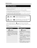
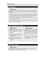
Page 2: ... handy for your quick reference in necessary If not provided with proper prevention it can cause death or fatal injury or considerable loss of property If not properly observed it can cause a hazard situation to result in severe or slight injury or a loss of property WARNING CAUTION CAUTION Safety Precautions Design Precautions Do not run I O signal lines near to high voltage line or power line Se...

Page 3: ...r like wire scraps should not enter into the module It can cause a fire disorder or malfunction CAUTION Test Run and Maintenance Precautions Do not contact the terminals while the power is applied It can cause malfunction When cleaning or driving a terminal screw perform them after the power has been turned off Do not perform works while the power is applied which can cause disorder or malfunction...

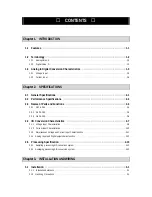
Page 4: ...1 G3F AD3A 2 4 2 3 2 G4F AD3A 2 5 2 3 3 G6F AD2A 2 6 2 4 I O Conversion Characteristics 2 7 2 4 1 Voltage Input Characteristics 2 8 2 4 2 Current Input Characteristics 2 10 2 4 3 Simultaneous Voltage and Current Input Characteristics 2 11 2 4 4 Analog input and Digital output characteristics 2 12 2 5 Processing Specification 2 13 2 5 1 Sampling processing A D conversion system 2 13 2 5 2 Averaging...

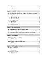
Page 5: ...G 5 1 Programming for Distinction of A DConversion Value 5 1 5 2 Programming for Display of A DConversion Value and Error Code on BCD Display 5 5 5 3 Programming for Loading the A D Conversion Module on Remote I O Station 5 8 Chapter6 Buffer Memory 6 1 The configuration of buffer memory 6 1 6 1 1 G6F AD2A 6 1 6 1 2 G3F AD3A G4F AD3A 6 2 6 2 The contents and description of buffer memory 6 3 6 2 1 G...

Page 6: ... Example Programming 8 3 8 2 1 A program for comparision of A D conversion value 8 3 8 2 2 Output the analog input value by 7 segment display 8 5 8 2 3 An A D module mounted on a remote station 8 7 Chapter9 DIMENSIONS 9 1 G3F AD3A Dimensions 9 1 9 2 G4F AD3A Dimensions 9 2 9 3 G6F AD2A Dimensions 9 3 ...

Page 7: ... conversion modul e The A D conversion modul e is to convert an analog input sig nal voltage or current from external devices into a 12 bi tsi gned binary digital value 1 1 Features 1 Mul t i channel analog to digital conversion is possible with a single A D modul e G6F AD2A 4 channels G4F AD3A and G3F AD3A 8 channels 2 The select of voltage input or current input is possible by channel of A D mod...

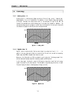
Page 8: ...le only digital values Figure 1 1 Analog value 1 2 2 Digital value D D igital value is adi screte data that are described in num bers such as 0 1 2 In general a binary code system t hat are consi st of 0 off and 1 on is used for expressing di gital value Also BCD or hexadecimal values are used Because the CPU module of PLC can handle dig ital value only the analog signal from external devices shou...

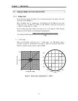
Page 9: ...put range the digital output is varied in the range of 0 4000 Therefore the resolution of the A D module is obtained by following equation 1 1 5VDC range W h e n the A D module operates with 1 5VDC range the 1VDC anal og input is convert ed to digital 0 and the 5VDC anal og input is converted into digital output 4000 Therefore the resolution per 1 digital value is 0 001VDC Figure 1 3 A D conversio...

Page 10: ...e W h e n the A D m odule operates with 1 0 10VDC range the 10VDC analog input is convert ed to di gital 0 and the1 0VDC anal og input is converted into digital output 4000 Therefore the resolution per 1 digital value is 0 005VDC Figure1 5 A D conversion characteristic 10 10VDC 2000 2001 2002 1998 1999 5 000V 5 0025V 4 9975V 5 005V 4 995V 4000 2000 0 5V 10V Analog input voltage D i g ital output v...

Page 11: ...on 1 4 20mA range W h e n t he A D m o d u le operates with 4 20m A range the 4m A a n a log input is converted to digital 0 and the 20m A analog input is converted into digital output 4000 Therefore the resolution per 1 digital value is 0 004m A Figure 1 6 A D conversion characteristic 4 20mA 4000 current input Minimum current input Maximum module A D of Resolution 2000 2001 2002 1998 1999 12 000...

Page 12: ... V LGIS Standard Electrostatic discharge Voltage 4kV contact discharge IEC 61131 2 IEC1000 4 2 Radiated electromagnetic field 27 500 MHz 10 V m IEC 61131 2 IEC1000 4 3 Modules All power modules Digital I Os Ue 24 V Digital I Os Ue 24 V Analog I Os communication I Os Noise immunity Fast transient burst noise Voltage 2 kV 1 kV 0 25 kV IEC 61131 2 IEC1000 4 4 Operating atmosphere Free from corrosive ...

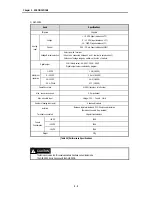
Page 13: ... program Digital output 16 bit binary value 1 5VDC 1 mV 1 4000 0 10VDC 2 5 mV 1 4000 Maximum resolution DC 4 20mA 4 1 4000 Overall Accuracy 0 5 accuracy to full scale Max conversion speed 5 0 ms channel Max absolute input Voltage 15V Current 25mA Number of analog input point 8 channels module Isolation Between input terminals and PLC Photo coupler isolation Between channels Non isolated Terminals ...

Page 14: ...ut value is selected by program 1 5VDC 1 mV 1 4000 0 10VDC 2 5 mV 1 4000 10 10VDC 5 mV 1 4000 Maximum resolution DC 4 20mA 4 1 4000 Overall Accuracy 0 5 accuracy to full scale Max conversion speed 5 0 ms channel Max absolute input Voltage 15V Current 25mA Number of analog input point 4 channels module Isolation Between input terminals and PLC Photo coupler isolation Between channels Non isolated T...

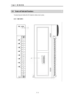
Page 15: ...Chapter 2 SPECIFICATIONS 2 4 The names of parts and functionsof the A D conversion module are shown as below 2 3 1 G3F AD3A 2 3 Names of Parts and Functions ...

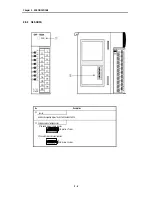
Page 16: ...dicates the operating status of the G3F AD3AandG4F AD3A Selection switch of voltage current 1 The switch status at voltage selection The switch locates off status 2 The switch statues at current selection The switch locates on status On 1 2 3 4 5 6 7 8 On 1 2 3 4 5 6 7 8 ...

Page 17: ...A No Description RUN LED Indicates the operating status of the G6F AD2A Selection switch of voltage current AnalogInput InputRangeSelectionSwitch DC1 5V DC0 10V Voltage DC 10 10V Current DC4 20mA 1 2 3 J1 J2 1 2 3 J1 J2 1 2 3 J1 J2 1 2 3 J1 J2 ...

Page 18: ...2 2 The voltage or current input for a channel is selected by analog input selection switch and the value of Offset Gain can not be changed because it is fixed Fig 2 1 I O Conversion Characteristics REMARK 1 Theanalogoutputvalueofover4047or 48is fixed as 4047 or 48 2 Keep the input voltage and current not to exceed 15V and 25mA 2 4 I O Conversion Characteristics Practical analog input range Digita...

Page 19: ... Inputselectionswitchhastobelocatedatoff 1 Voltageinputrange DC0 10V Digital output value for input voltage is shown as follows Analoginputvoltage V 0 12 0 2 5 5 7 5 10 10 12 Digital output value 48 0 1000 2000 3000 4000 4047 Input selection switch Off Voltage This switch is located on the side of module On 1 2 3 4 5 6 7 8 CH0 1 2 3 4 5 6 7 Number of channel Practical analog input range Digital Ou...

Page 20: ...ange selection switch 0 952 1 2 3 4 5 5 048 48 0 1000 2000 3000 4000 4047 Digital output value 2048 2000 1000 0 1000 2000 2047 2 Voltageinputrange DC0 10 V Digital output value for input voltage is shown as follows Analoginputvoltage V Input range selection switch 0 12 0 2 5 5 7 5 10 10 12 48 0 1000 2000 3000 4000 4047 Digital output value 2048 2000 1000 0 1000 2000 2047 3 Voltageinputrange DC 10 ...

Page 21: ...ut value 48 0 1000 2000 3000 4000 4047 2 G6F AD2A Digital output value for input voltage is shown as follows Analoginputcurrent mA Input range selection switch 3 808 4 8 12 16 20 20 192 48 0 1000 2000 3000 4000 4047 Digitaloutputvalue 2048 2000 1000 0 1000 2000 2047 It has to be connected between V and I terminal to select current Input selection switch On 1 2 3 4 5 6 7 8 On Current This switch is...

Page 22: ...al output value 48 0 1000 2000 3000 4000 4047 2 G6F AD2A For simultaneous useof voltage and current input the available input voltage rage is 0 5VDC only Digital output value for analog input is shown as follows Analoginput Voltage DC1 5V 0 952 1 2 3 4 5 5 048 CurrentDC4 20mA 3 808 4 8 12 16 20 20 192 48 0 1000 2000 3000 4000 4047 Digital output value 2048 2000 1000 0 1000 2000 2047 Ex channel for...

Page 23: ... 032 12 036 12 036 12 040 Analog input and Digital output Analog input and digital output value Digital output value 2000 2001 2002 2003 2004 2005 2006 2007 2008 2009 No Input range Digital output value Resolution Analog input value ℵ DC 10 10V 5mV 0 000 0 005 0 005 0 010 ℑ DC 0 10V 2 5 mV 5 000 5 0025 5 0025 5 005 5 005 5 0075 5 0075 5 010 ℑ DC 1 5V 1mV 3 000 3 001 3 001 3 002 3 002 3 003 3 003 3...

Page 24: ...onversion time 5 ms The process time when 4 channels is used for example will be 20 msec 4 5 ms 2 5 2AveragingprocessingA Dconversionsystem The A D module makes the A D conversion for any channels to which averaging processing has been specified from the CPU Using a pres et count an average is calculated excluding the maximum value and the minimum value and stored to the buffer memory The preset c...

Page 25: ...un the PLC system is exposed to corrosive or inflammable gas the PLC system is exposed to conductive powder oil mist salt or organic solvent 2 Installing and wiring During wiring or other work do not allow any wire scraps to enter into the module Install the module on location that is convenient for operation Be sure that it is not located near high voltage equipment on the same panel Be sure to i...

Page 26: ...cuit which leads to damage and or mis operation Be careful not to connect external power supply with wrong polarity Separate external wiring sufficiently from high voltage and power supply cable not to cause induced noise or malfunction of module 3 2 2 Wiring examples 1 G6F AD2A Voltage input Current input 1 Use a two core twisted pair shielded cable 2 If noise is expected ground the cable and FG ...

Page 27: ... Usea two core twisted pair shielded cable 2 If noise is expected ground the cable as shown in figure R CH7 CH0 Voltage current selection switch 1 2 R 1 R R R R R Voltage range selection switch R 1 1 2 R CH7 CH0 Voltage current selection switch R R R R R R Voltage range selection switch R ...

Page 28: ...D AD2ARD ADR62RD Reading A D convertedvalue array Type 3 AD3RD AD3RD AD2RD Reading A D convertedvalue Single Type 4 1 Registration of the Function Block for A D ConversionModule on the GMWIN Project P Library Insertion I G3F AD3A 1 Special 3fb AD3INI AD3ARD AD3RD 2 Remote3 3fb ADR3INI ADR3RD 3 Remote4 3fb ADR3INI ADR3RD G4F AD3A 1 Special 4fb AD3INI AD3ARD AD3RD 2 Remote4 4fb ADR3INI ADR3RD 3 Remo...

Page 29: ...8 AnalogInputData Type Specification Area Output digital data type for each channel is specified in this area 0 is for the range of 1 5VDC andDC4 20mA 1 is for the range of 0 10VDC AVG_ EN BOOL 8 Enable Disable of Average processing 0is for thesampling processing 1is for the average processing of the number of times Input AVG_ NUM USINT 8 Set a constant of the average processing of the number of t...

Page 30: ...sabled channels are specified to 0 DATA TYPE BOOL 4 DigitalOutputData Type Specification Area 0 is for the range of 48 4047 1 is for the range of 2048 2047 AVG_ EN BOOL 4 Enable Disable ofAverage processing 0is for thesampling processing 1is for the average processing forthe number of times Input AVG_ NUM USINT 4 Set a constant of the average processing of the number of times Setting range 2 255 D...

Page 31: ...lue Output Area Output data range 48 4047 REMARK BOOL 8 and USINT 8 of data type means that the number of element is 8 and also this means the whole number of channels and channel number 2 G6F AD2A Array type of function block for reading is performed for allchannels in module and the specified channel is used to read output variable of data displayed from A D conversion digital value Function blo...

Page 32: ...curred during function block initialization the error code number is written output DATA INT A D Conversion Value Output Area Output data range 47 4048 2 G6F AD2A Single type of function block for reading the module isperformed for only one channel and the specified channel is used to read output variable of data displayed from A D conversion digital value Function block I O Variable Data type Des...

Page 33: ...ting range 0 to 7 CH BOOL 8 Available Channel Specification Area Available channels are specified in this area Enabled channels are specified to 1 and disabled channels are specified to 0 TYPE BOOL 8 Output Data Type Specification Area Output digital data type for each channel is specified in this area 0 is for the range of 1 5VDC and DC 4 20mA 1 is for the range of0 10VDC AVG_ EN BOOL 8 Average P...

Page 34: ...le Channel Specification Area Available channels are specified in this area Enabled channels are specified to 1 and disabled channels are specified to 0 DATA TYPE BOOL 4 Output Data Type Specification Area Output digital data type for each channel is specified in this area 0 is for the r ange of 48 to 4047 1 is for the range of 2048 to 2047 AVG_ EN BOOL 4 Average Process Enable Specification Area ...

Page 35: ...ted is written on this area Setting range 0 to 7 Input CH BOOL 8 Available Channel Specification Area Available channels are specified in this area Enabled channels are specified to 1 and disabled channels are specified to 0 NDR BOOL When function block execution is completed with no error 1 is written During the scan which the execution condition has been made 1 is continuing and at the next scan...

Page 36: ...en on this area Setting range 0 to 7 Input CH BOOL 4 Available Channel Specification Area Available channels are specified in this area Enabled channels are specified to 1 and disabled channels are specified to 0 NDR BOOL When function block execution is completed with no error 1 is written During the scan which the execution condition has been made 1 is continuing and at the next scan 0 is writte...

Page 37: ...dule s shared memory error О О О Contact the service station 9 The available channels are not specified О О Make a correct specification of the available channel on the initialize function block 17 Local Average number exceeding the proper range О Correct the value to the proper range Number 2 to255 128 H W error of the communication module for remote О О See the manual for the remote communicatio...

Page 38: ...Analog input current input DC4 20 mA 3 Average processing setting channel 2 100 times channel 3 50 times 3 Descriptions of the Program 1 The digital value less than 2 000 of channel 0turns Q0 1 0 on 2 The digital value more than 3 600 of channel 2turns Q0 1 1 on 3 The digital value more than 2 000 or same and less than 3 600 or same of channel4 turns Q0 1 2 on 4 The digital value of the same as 2 ...

Page 39: ... the functionblock initialization Base location numberspecification Slot location Number specification Available channel enable specification Error code display in the processing of the read function block Channel operation display in the proces s ing of read function block initialization Data display of A D conversion value of enabled channel Normal completion of A D conve rsion reading A D conve...

Page 40: ...utput variables on the program Specifying channels This denotes 4 channels Select this and this screen appears Channel No To specify channel enable disable Select this and this screen appears To select previous Ch To select next Ch Enabled channel 1 Disabled channel 0 ...

Page 41: ...ance AVG_EN VAR ARRAY 0 7 OF BOOL 0 1 0 1 0 0 0 0 AVG_NUM VAR ARRAY 0 7 OF USINT 0 0 100 50 0 0 0 0 DATA VAR ARRAY 0 7 OF INT DATATYPE VAR ARRAY 0 7 OF BOOL 0 0 0 0 0 0 0 0 INI_ACT VAR ARRAY 0 7 OF BOOL INI_STAT VAR USINT RD_ACT VAR ARRAY 0 7 OF BOOL RD_STAT VAR USINT READY VAR BOOL START VAR BOOL Variable Name Var_Kind Data Type AT Address Initial Value ...

Page 42: ...riptions of the Program 1 I0 0 0 turning On leads to the initial setting of A Dconversion module 2 I0 0 1 turning On leads to displaying A D conversion value on the BCD display Q0 1 0 to Q0 1 15 3 I0 0 2turning On leads to displaying error code of function block on the BCD display Q0 2 0 to Q0 2 7 Initialize I0 0 0 Display error code with BCD I0 0 1 I0 0 2 Display A D conversion data with BCD Digi...

Page 43: ...display in the processing of the reading function block Data display of A D conversion value of enabled channel Slot location number specification A D conversion read has been completed normally This program converts the integer type of the A D conversion value CH0_DATA into BCD data type to display onto the BDC digital display Command for displaying the error code onto BCD digital display Error c...

Page 44: ...ance AD_RD VAR FB Instance AVG_EN VAR ARRAY 0 7 OF BOOL 1 0 0 0 0 0 0 0 CH0_DATA VAR INT DATA VAR DINT DATATYPE VAR ARRAY 0 7 OF BOOL 0 0 0 0 0 0 0 0 INI_ACT VAR ARRAY 0 7 OF BOOL INI_STAT VAR USINT AVG_NUM VAR ARRAY 0 7 OF UINT 10 0 0 0 0 0 0 0 RD_STAT VAR USINT START VAR BOOL Variable Name Var_Kind Data Type AT Address Initial Value ...

Page 45: ...ting value 50 times 3 Descriptions of the Program 1 The digital value less than 2000of channel 0 turns Q0 1 0 on 2 Thedigitalvaluemorethan 2000 or same and less than 10 000 or same of channel 0 turns Q0 1 1 on 3 Thedigitalvaluemorethan 3 000 or same and less than 12 000 of channel 0 turns Q0 1 2 on 4 Thedigitalvaluemorethan 4 000 or sa me of channel 0 turns Q0 1 3 on GM4 PA1A G4L RBEA G4F AD3A Rem...

Page 46: ... in processing of initializationfunctionblock Error code display in processing of initializationfunctionblock Normal channel operation display The digital value less than 2000 of channel 0 turns Q0 1 0 on The digital value more than 2000 or same and less than 3000 or same turns Q0 1 1 on Thedigitalvaluemorethan 3000 or same and less than 4000 turns Q0 1 2 on The digital value more than 12000 or sa...

Page 47: ...ance AVG_EN VAR ARRAY 0 7 OF BOOL 1 0 0 0 0 0 0 0 AVG_SEL VAR ARRAY 0 7 OF BOOL 1 0 0 0 0 0 0 0 INPUTTYPE VAR ARRAY 0 7 OF BOOL 0 0 0 0 0 0 0 0 INI_ACT VAR ARRAY 0 7 OF BOOL INI_ERR VAR BOOL INI_STAT VAR USINT AVG_NUM VAR ARRAY 0 7 OF UINT 50 0 0 0 0 0 0 0 RD_STAT VAR ARRAY 0 7 OF BOOL RD_ERR VAR BOOL RD_STAT VAR USINT READY VAR BOOL Variable Name Var_Kind Data Type AT Address Initial Value ...

Page 48: ...g count of Ch2 Assign the count of Avg processing of Ch2 h02 R W 06 Avg count of Ch3 Assign the count of Avg processing of Ch3 h02 R W 07 Dataenable Make enable the new setting of buffer 0 6 h00 R W 08 Ch0 digital output value Digital output value of channel 0 R 2 09 Ch1 digital output value Digital output value of channel 1 R 10 Ch2 digital output value Digital output value of channel 2 R 11 Ch3 ...

Page 49: ...the new setting of buffer 0 10 h00 R W 12 Ch0 digital output value Digital output value of channel 0 R 13 Ch1 digital output value Digital output value of channel 1 R 14 Ch2 digital output value Digital output value of channel 2 R 15 Ch3 digital output value Digital output value of channel 3 R 16 Ch4 digital output value Digital output value of channel 4 R 17 Ch5 digital output value Digital outpu...

Page 50: ... bit5 bit4 bit3 bit2 bit1 bit0 Ch3 Ch2 Ch1 Ch0 Example To enable channel 1 and 2 Write h0006 turn on bit 1 and 2 to buffer 00 and sampling time is obtained as 2 5ms 10ms 2 Output data range Address 01 Only G6F AD2A has the function of selecting the range of digital output data It is not available with G3F AD3A and G4F AD3A Each channel can be set independently Turn on the corresponding bit as 1 to...

Page 51: ...ss Description 03 The number of averaging count of channel0 04 The number of averaging count of channel 1 05 The number of averaging count of channel 2 06 The number of averaging count of channel 3 5 Data enable Address 07 By turning on the bit 0 of address 07 the contents of address 00 06 are validated While the bit 0 of address 07 is off the A D module operates according to the previous value of...

Page 52: ... of channel 1 10 The digital output value of channel 2 11 The digital output value of channel 3 7 Channel status Address 12 Indicates a channel is operating or not by turning on off the corresponding bit bit15 bit14 bit13 bit12 bit11 bit10 bit9 bit8 bit7 bit6 bit5 bit4 bit3 bit2 bit1 bit0 Ch3 Ch2 Ch1 Ch0 8 Error code Address 13 16 Shows an error code when an error occurred Error code Description h...

Page 53: ...AD3A Write h000D turn on bit 1 2 and 3 to buffer 00 and sampling time is obtained as 3 5ms 15ms 2 Input voltage current type Address 01 This function is available with G3F AD3A and G4F AD3A With the G6F AD2A the input voltage current type isn t set by sequence program Turn on the cor responding bit as 1 to set the input voltage current type as 0 10 VDC The default value is 0 1 5 VDC and DC4 20mA W...

Page 54: ...ing count of channel 1 05 The number of averaging count of channel 2 06 The number of averaging count of channel 3 07 The number of averaging count of channel 4 08 The number of averaging count of channel 5 09 The number of averaging count of channel 6 10 The number of averaging count of channel 7 5 Data enable Address 11 By turning on the bit 0 of address 07 the contents of address 00 06 are vali...

Page 55: ...nel 3 16 The digital output value of channel 4 17 The digital output value of channel5 18 The digital output value of channel 6 19 The digital output value of channel 7 7 Channel status Address 20 Indicates a channel is operating or not by turning on off the corresponding bit bit15 bit14 bit13 bit12 bit11 bit10 bit9 bit8 bit7 bit6 bit5 bit4 bit3 bit2 bit1 bit0 Ch7 Ch6 Ch5 Ch4 Ch3 Ch2 Ch1 Ch0 8 Err...

Page 56: ... A D module is mounted S Start address of buffer memory to be read D Start address of CPU memory at which read data is stored n2 Number of word to be read Available only when do not use computer link module or data link module 1 Functions Reads the data of n2 words which start at the address specified as S of buffer memory inside the special module mounted at the slot n1 and stores the data into t...

Page 57: ...mory of the A D module G4F AD3A mounted at the slot 3 and stores them to the D0014 D0015 of CPU module Program that reads address 09 10 of buffer memory of the A D module G6F AD2A mounted at the slot 3 and stores them to the D0014 D0015 of CPU module G4F AD3A G6F AD2A Buffer memory of A D module CPU module 12 07 D0012 13 08 D0013 14 09 2001 D0014 2001 15 10 1999 2 words D0015 1999 2 words 16 11 D0...

Page 58: ... byte Station number of Fnet remote module n Number of words to be read D Start address of destination device of self station SS Device at which the link status is stored Available only when do not use computer link module or data link module 1 Functions Reads the data of n2 words which starts at the address specified as S of buffer memory inside the special function module of remote station stati...

Page 59: ...s followings Module Code G3F AD3A h40 G4F AD3A hC0 G6F AD2A h02 For the codes of other special function modules please refer the user s manual of the related special function module An operation error occurs when S n2 1 or D n2 1 is exceeds the range of specified device Execution conditions Input condition RGET Executed only once Executed only once Fnet remote module Fnet module Station No st ...

Page 60: ...of self station System configuration Self station GM4 PA2A K4P 15AS G4I D22A G4I D22A G4L FUEA Station No h01 G4L FUEA Station No h02 G4Q RY2A slot 0 slot 1 slot 2 slot 3 slot 4 Remote station GM3 PA2A G3L RBEA Station No h1D G3I D22A G3F AD3A G3Q RY2A slot 0 slot 1 slot 2 Example program sl upper byte à the code of remote module is hC0 lower byteà slot number of Fnet module of self station is h03...

Page 61: ...ed D Start address of buffer memory at which data will be written D Start address of source data of CPU module n2 Number of word to be written Available only when do not use computer link module or data link module 1 Functions Write the data of n2 words which start at the address specified as S of CPU and transfer the data into the block starting at the address specified as D of buffer memory insi...

Page 62: ...e Execution conditions Input condition PUT PUTP 2 Program example Program that write 3 words of D0049 D0051 of CPU module to the address 02 04 of buffer memory of the A D module mounted at the slot 3 Buffer memory of A D module CPU module 01 D0048 02 h0003 D0049 h0003 03 h0020 D0050 h0020 04 h0020 3 words D0051 h0020 3 words 05 D0052 Executed per scan Executed per scan Executed only once Executed ...

Page 63: ...tion module st Lower byte Station number of Fnet remote module n Number of words to be read S Start address of device at which source data is stored self station SS Device at which the link status is stored Available only when do not use computer link module or data link module 1 Functions Write the data of n words which start at the device specified as S to the block which begin with the address ...

Page 64: ...s followings Module Code G3F AD3A h40 G4F AD3A hC0 G6F AD2A h02 For the codes of other special function modules please refer the user s manual of the related special function module An operation error occurs when S n2 1 or D n2 1 is exceeds the range of specified device Execution conditions Input condition RPUT Executed only once Executed only once Fnet remote module Fnet module Station No st ...

Page 65: ...em configuration Self station GM4 PA2A K4P 15AS G4I D22A G4I D22A G4L FUEA Station No h01 G4L FUEA Station No h02 G4Q RY2A slot 0 slot 1 slot 2 slot 3 slot 4 Remote station GM3 PA2A G3L RBEA Station No h0E G3I D22A G3Q RY2A G3F AD3A slot 0 slot 1 slot 2 Example program sl upper byte à the code of remote module is hC0 lower byteà slot number of Fnet module of self station is h02 st upper byte à slo...

Page 66: ...bit14 bit13 bit12 bit11 bit10 bit9 bit8 bit7 bit6 bit5 bit4 bit3 bit2 bit1 bit0 Bit 0 Turns on during 1 scan after the communication is completed normally Bit 1 Turns on during 1 scan after a communication error is occurred Bit 2 7 Not used Bit 8 15 When the bit 1 turns on the corresponding error code is stored Error code Error Done ...

Page 67: ...016 D0116 00001 Slot number Buffer memory Data No of words Channel to be used use channel 0 1 and 3 Assign analog input range DC4 20mA Assignaverage processing channel channel 0 and 3 Set Averaging count of channel 0 100 times Set Averaging count of channel 3 50 times Validate the new setting value Execution condition Execution condition Slot number Buffer memory Destination of data No of words Re...

Page 68: ...analog input range DC4 20mA Assignaverage processing channel channel 0 and 3 Set Averaging count of channel 0 100 times Set Averaging count of channel 3 50 times Validate the new setting value Execution condition Execution condition Slot number Buffer memory Destination of data No of words Read the A D converted valueofchannel0 and store it into D0112 Read the A D converted valueofchannel3 and sto...

Page 69: ...20mA 1 h0000 3 Averaging processing enable Ch 2 4 2 h0014 Ch2 100 times 5 h0064 4 Averaging count Ch 4 50 times 7 h0032 5 Validate setting 11 h0001 3 Description of program Turns on P0010 bit when the digital value of channel 0 is less than 2000 Turns on P0011 bit when the digital value of channel 2 is greater than 3600 Turns onP0012 bit when the digital value of channel 4 is in the range of 2000 ...

Page 70: ...idate the new setting value Slot number Buffer memory Destination of data No of words Read the A D converted valueofchannel0 and store itinto D0012 Read the A D converted valueofchannel2 and store it into D0014 Read the A D converted valueofchannel4 and store it into D0016 Read the error code of channel 0 and store it into D0021 Read the error code of channel 2 and store it into D0 023 Read the er...

Page 71: ... 0 2 h0001 4 Averaging count Ch 0 10 times 3 h000A 5 Validate setting 7 h0001 3 Description of program When the P0000 is on initialize the A D module When the P0001 is on read the digital value of channel 0 from buffer memory of A D module and store it into the D0008 When the P0002 is on outputthe contents of D0008 to the 7 segment display GM6 PAFB K3P 07AS G6I D22A G6Q TR2A G6F AD2A P000 P001 P00...

Page 72: ...gn digital output range 48 4047 Assignaverage processing channel channel 0 Set Averaging count of channel 0 10 times Validate the new setting value Slot number Buffer memory Destination of data No of words Read the A D converted valueofchannel0 and store it into D0008 Read the error code of channel 0 and store it into D0013 P0001 P0000 SET M0000 M0000 M0000 Set M0000 to execute aboveprogramblock o...

Page 73: ... Ch 0 10 times 3 h000A 5 Validate setting 7 h0001 3 Description of program When the digital converted value of channel 0 of remote A D module is less than 2000 turns on P0010of self station When the digital converted value of channel 0 of remote A D module is 2000 2999 turns on P0011 of self station When the digital converted value of channel 0 of remote A D module is 3000 3999 turns on P0012 of s...

Page 74: ...11 00011 00001 M001 P0000 Send the setting data to theremoteA Dmodule via Fnet module at slot 2 RGET hC002 h0001 D0012 00012 00001 M002 F0093 P0000 Read buffer 12 of remote A Dmoduleper1 second andstoreitto D0012 of self station Buffer memory Start address of data No of w ords Link status Remotecode of A D module Slot number of A D module Slot number of Fnet module Stationnumberof Fnetremotemodule...

Page 75: ...Chapter 9 Dimension 9 1 9 Dimension 9 1 G3F AD3A Unit mm ...

Page 76: ...Chapter 9 Dimension 9 2 9 2 G4F AD3A Unit mm ...

Page 77: ...Chapter 9 Dimension 9 3 9 3 G6F AD2A Unit mm ...

Page 78: ...Chapter 9 Dimension 9 4 ...

Reviews: