90
SC100/200 Series Function Block Application Manual EM-6460-C
6.2 RELAY SEQUENCE
6.2.1 GENERAL DESCRIPTIONS
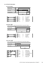
Software relay circuits have the following differences from actual relay circuits. They must be carefully considered when you
build software logic sequence programs, but on the other part this means new possibilities of configuring virtual circuits which
are not possible by actual relays.
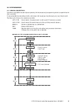
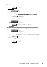
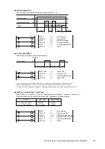
1) In every computation cycle, external input is taken in, processed through commands in the order of function block num-
bers and ITEM numbers, and provided as output at once at the end of the cycle. An upstream block utilizing a down-
stream block result can process such command only in a next cycle.
2) If one switching device is operated multiple times in one cycle, operation result at the most downstream block prevails.
3) One contact or coil can be used multiple times as conditions. There is no limitation applicable with actual mechanical
relays.
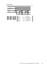
4) Relay circuit operations using common power supply lines, such as interlocking circuit or shutdown circuit, are not pos-
sible with the software relay circuits. Build such circuits separately in downstream blocks.
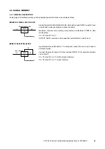
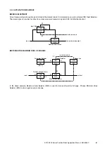
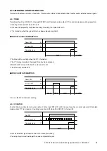
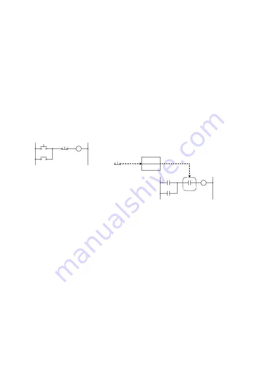
5) N.C. contact in an actual relay circuit may be expressed as N.O. contact in the software function block. (See the example
below.)
Y
DI 1
DI 2
Y
Y
ON
■
RELAY CIRCUIT
■
FUNCTION BLOCK
All external inputs are replaced with status outputs via Field Terminal
or Communication Terminal blocks. N.C. PBS input is handled as N.O.
contact in the function block descriptions.
OFF
Y
G05
DI
X0
OFF

