9
SC100/200 Series Function Block Application Manual EM-6460-C
1.4 CODING PRINCIPLE
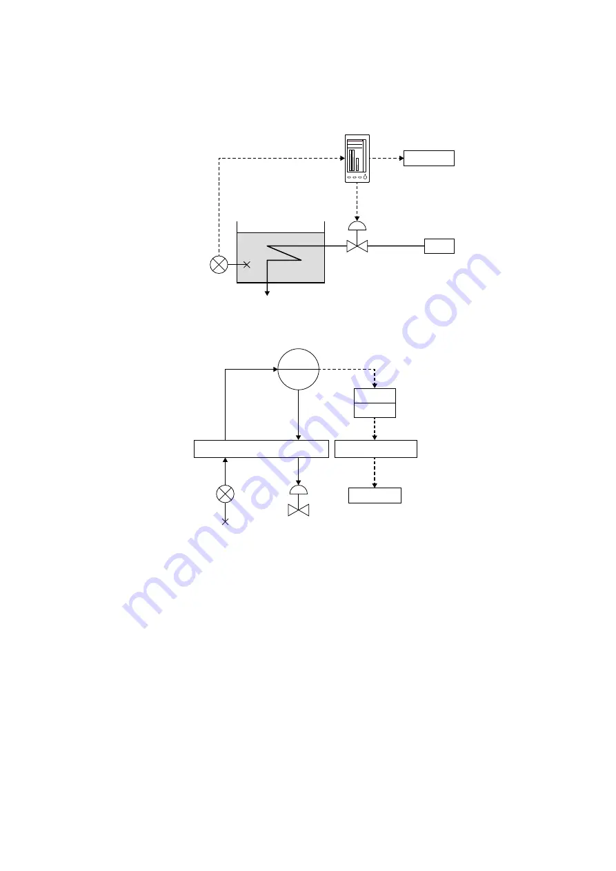
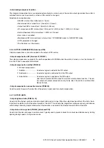
A temperature control loop with one PID control block is given as an example to explain how to proceed in coding.
(1) Determining necessary function blocks
• Basic PID is used for control function.
• High temperature limit is supplied to activate an alarm at DO terminal.
(2) Control Block
• Register Basic PID to Group 02 (or Group 03).
• Specify PV input from the SCxxx Extension Field Terminal 1 (Group 04).
• Set temperature range to 0.0-80.0°C, with ITEM 82 (upper range) set to ‘800,’ ITEM 83 (lower range) set to ‘0’
and ITEM 84 (decimal point position) set to ‘1.’
• Set reverse control action, with ITEM 40 set to ‘1’ so that the valve closes at MV output 4 mA.
(3) Sequential Control Block
• Register Sequential Control Block to Group 81.
• Write a command to turn on DO terminal at high alarm setpoint.
• Connect Basic PID terminal ‘01’ to trigger the alarm.
steam
annunciator
TIC (0-80°C)
control valve
(reverse action)
H
■
LOOP CONFIGURATION
annunciator
TIC
G02
H
PV
MV
MV
DO
PV
■
BLOCK DIAGRAM
G04 : Field Terminal
G05 : Field Terminal
SEQ
G81
hot water tank
temperature
sensor
Sequence
temp


