12.0
COMMUNICATION (OPTIONAL)
www.maxcessintl.com
MAGPOWR Spyder-Plus
MI 850A320 1 M
Page 54 of 60
Spyder Data
Number Modbus Registers
Comments
BYTE
8-bit Unsigned Byte
1
High byte forced to 0
UINT16
16-bit Unsigned Integer
1
UINT32
32-bit Unsigned Integer
2
FLOAT
4-byte Floating Point
2
STRING
32-byte Strings
16
Since some data values are contained in multiple Modbus registers the function code 16, Write Multiple Registers
must be used to write these data values. If a write occurs to only one of the Modbus registers corresponding to a
two-word parameter then the Spyder will ignore the write. If a write to a 16 word string does not write all 16
registers then the Spyder will ignore the write. This prevents the Spyder from receiving only part of a data value.
This could be problematic if Setpoint Tension or other control parameter was corrupted by only writing a portion of
the new data value. Reads do not have this restriction.
The Modbus standard specifies data as being transmitted Most Significant Byte first. To support master devices
which transmit data Least Significant Byte first the Spyder allows switching between the two. For multiple register
data there is a configuration parameter to specify whether words (registers) are transmitted Most Significant Word
first or last. These two configuration parameters are in the Network menu. The default is Most Significant Byte first
and Most Significant Word first. Note: Strings are always transmitted left most character first.
12.7
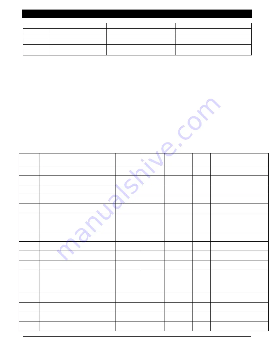
MODBUS PARAMETER LIST
This table lists all the Spyder parameters and their minimum and maximum values. Modbus register addresses are
shown in hexadecimal format in the table. Control type abbreviations are LC = Load Cell Control, DT = Dancer
Torque Control, DS = Dancer Speed Control, OPT = Open Loop Tension based on Diameter Control.
Starting
Modbus
Register
Parameter Name
Parameter
Format
Parameter
Type
Used with
Control
Types
Read /
Write
Range
0x01
Use DHCP
BYTE
Data
LC, DT, DS,
OPT
Read /
Write
0 = No,
1 = Yes
0x02
IP Address
UINT32
Cal
LC, DT, DS,
OPT
Read /
Write
{0.0.0.0 - 255.255.255.255}
0x04
Subnet Mask
UINT32
Data
LC, DT, DS,
OPT
Read /
Write
{0.0.0.0 - 255.255.255.255}
0x06
Gateway Address
UINT32
Data
LC, DT, DS,
OPT
Read /
Write
{0.0.0.0 - 255.255.255.255}
0x08
FTP Address
UINT32
Data
LC, DT, DS,
OPT
Read /
Write
{0.0.0.0 - 255.255.255.255}
0x0A
FTP Program Number
UINT32
Data
LC, DT, DS,
OPT
Read /
Write
920Axxx.yyy
xxx,yyy={0 - 999}
xxx = High Word
yyy = Low Word
0x0C
FTP Directory
STRING
Data
LC, DT, DS,
OPT
Read /
Write
31 Characters Maximum
0x1C
FTP User Name
STRING
Data
LC, DT, DS,
OPT
Read /
Write
31 Characters Maximum
0x2C
FTP Password
STRING
Data
LC, DT, DS,
OPT
Read /
Write
31 Characters Maximum
0x3C
Screen Contrast
BYTE
Cal
LC, DT, DS,
OPT
Read /
Write
{ 0 - 255 }
0x3D
Language
BYTE
Data
LC, DT, DS,
OPT
Read /
Write
0 = English
1 = French
2 = German
3 = Italian
4 = Spanish
0x3E
Remote Setpoint Tension
FLOAT
Data
LC, OPT
Read /
Write
{ 0.0 - 99999.0 } lb.
0x40
Setpoint Source
BYTE
Data
LC, DT, DS,
OPT
Read /
Write
0 = Analog
1 = Ethernet/Software
0x41
Taper Percent
FLOAT
Data
LC, OPT
Read /
Write
{ 0.0 - 100.0 } %
0x43
Is Taper Setup
BYTE
Cal
LC
Read /
Write
0 = No
1 = Yes


