USB-1808X-OEM User's Guide
Functional Details
13
Counter input
Counter inputs can be read asynchronously under program control, or synchronously as part of a digital scan
group.
The
CTR0
and
CTR1
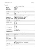
pins are 32-bit general-purpose counters that can accept frequency inputs up to 50 MHz.
The USB-1808X-OEM supports the following counter input modes:
Totalize
Period measurement
Pulse-width measurement
Counter input modes are programmable with software. Each mode supports additional counter operation
options.
Typically, when data is acquired with no counter operation options set, the count of each counter channel is set
to 0 and latched at the beginning of the acquisition.
When counter options are set the counters can concurrently monitor time periods, frequencies, pulses, and other
event-driven incremental occurrences directly from pulse-generators, limit switches, proximity switches, and
magnetic pick-ups.
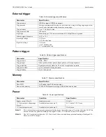
Counter input operations can be paced by the internal clock or by an external clock (
ICLKI
on page 15). They can be initiated by a digital trigger (
on page 15) or a pattern trigger
Synchronous I/O – mixing analog, digital, and counter scanning
on page 15 for information on running
counter input scans at the same time as other subsystem scans.
Totalize counter mode
The USB-1808X-OEM can be used as a high-speed pulse counter for general counting applications. The
internal counter increments when the TTL levels transition from low to high or from high to low.
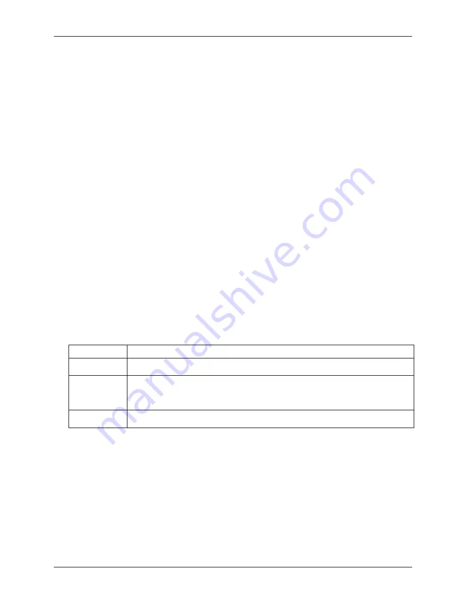
Each option supported in Totalize mode is explained in following table:
Totalize counter mode options
Counter option Description
Clear on read
The counter is cleared after each read (synchronous or asynchronous). The value of the counter
before it was cleared is latched and returned.
Range limit
When counting up: The counter rolls over to MINLIMIT (or stops if Non-recycle is set) when the
maximum count (specified by the MAXLIMIT value) is reached.
When counting down: The counter counts down to MINLIMIT and then rolls over to MAXLIMIT
(or stops if Non-recycle is set).
Non-recycle
The counter stops if a count overflow or underflow occurs (or, if Range limit is set, the MAXLIMIT
or MINLIMIT value is reached). Counting resumes if direction is reversed or the counter is reloaded.
Period measurement mode
Use period mode to measure the period of a signal at a counter channel's input. You can measure x1, x10, x100
or x1000 periods for 32-bit values. Four resolutions are available — 20 ns, 200 ns, 2000 ns, or 20,000 ns. All
period measurement mode options are software-selectable. The 100 MHz system clock is used as the timing
source. Periods from sub-microsecond to many seconds can be measured.
Pulse width measurement mode
Use pulse width mode to measure the time from the rising edge to the falling edge, or vice versa, on a signal on
a counter input. Four resolutions are available — 20 ns, 200 ns, 2000 ns, or 20,000 ns. All pulse width
measurement mode options are software selectable. The 100 MHz system clock is used as the timing source.
Pulse widths from sub-microsecond to many seconds can be measured.


