USB-1808X-OEM User's Guide
Functional Details
15
Figure 6. USB-1808X-OEM PWM timer channel
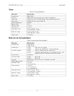
Timer output operations can be paced by the internal clock or by an external clock (
OCLKI
below). They can be initiated by a digital trigger (
Synchronous I/O – mixing analog, digital, and counter scanning
The USB-1808X-OEM can read analog, digital, and counter inputs, and generate up to two analog outputs and
one digital pattern output at the same time. Digital and counter inputs do not affect the overall A/D rate because
these inputs use no time slot in the scanning sequencer.
For example, one analog input channel can be scanned at the full 200 kS/s A/D rate along with digital and
counter input channels. Each analog channel can have a different gain, and counter and digital channels do not
need additional scanning bandwidth if there is at least one analog channel in the scan group. Digital input
channel sampling is done during the
dead time
of the scan period when no analog sampling is being done.
Clock I/O
The USB-1808X-OEM provides one external clock input (
ICLKI
) and one clock output (
ICLKO
) for input
operations.
Connect an external clock signal to
ICLKI
.
The pacer clock is available at
ICLKO
.
The USB-1808X-OEM provides one external clock input (
OCLKI
) and one clock output (
OCLKO
) for output
operations.
Connect an external clock signal to
OCLKI
.
The pacer clock is available at
OCLKO
.
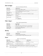
Digital triggering
The
ITRIG
(for triggering input operations) and
OTRIG
(for triggering output operations) pins are external
digital trigger inputs. The trigger mode is software-selectable for edge or level sensitive. Edge sensitive mode is
selectable for rising or falling. Level sensitive mode is selectable for high or low.
Pattern triggering
You can also start an input or output scan with a digital pattern trigger using DIO0 – DIO3. The pattern
represents the state of up to four bits on the port.
You specify the pattern and the trigger type with software. Supported trigger types are Above Pattern, Below
Pattern, Equal Pattern, and Not Equal Pattern. The scan begins when the trigger conditions are met.
The base clock is fixed at 100 MHz (10 ns). The trigger pattern must be held for five base clock cycles (50 ns)
to ensure that it is properly detected. The trigger latency is 1 scan clock 8 base clock cycles (80 ns).
Mask option
Use a bitmask to specify which bits to include or exclude from the pattern to detect. To include a bit in the
pattern, sets its value to 1. To exclude a bit from the pattern, sets its value to 0. Refer to the pattern and mask
values shown in Figure 7 and Figure 8.


