background image

6. MODBUS REGISTERS 

6 -  4 


Address 

Name and function 

Data 

type 

Read/ 

write 

Initial value 

Range 

Unit 

Saved 

to EEP-

ROM 

Para-

meter 

No. of 

Points/ 

No. of 

Registers 

Continuous 

read/ 

continuous 

write 

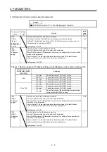
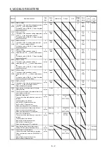
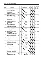
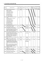
2B04  Cumulative command pulses (Cumulative 

command pulses) 
The cumulative command pulses are returned. 

bytes 

Reading  80000000h 

to 

7FFFFFFFh 

pulse     2 

Possible 

2B05  Command pulse frequency (Command pulse 

frequency) 
The command pulse frequency is returned. 

bytes 

Reading  80000000h 

to 

7FFFFFFFh 

kpulse/s  


2 Possible 

2B06  Analog speed command voltage (Analog 

speed command voltage) 
The analog speed command voltage is 
returned. 

bytes 

Read  8000h 

to 

7FFFh 

V   1 

Possible 

2B07  Analog torque limit voltage/Analog torque 

command voltage (Analog torque limit 
voltage/Analog torque command voltage) 
The analog torque limit voltage/analog torque 
command voltage is returned. 

bytes 

Reading   8000h 

to 

7FFFh 

V   1 

Possible 

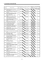
2B08  Regenerative load ratio (Regenerative load 

ratio) 
The regenerative load ratio is returned. 

bytes 

Reading   0000h 

to 

FFFFh 

%   1 

Possible 

2B09  Effective load ratio (Effective load ratio) 

The effective load ratio is returned. 

bytes 

Reading   0000h 

to 

FFFFh 

%   1 

Possible 

2B0A  Peak load ratio (Peak load ratio) 

The peak load ratio is returned. 

bytes 

Reading   0000h 

to 

FFFFh 

%   1 

Possible 

2B0B Instantaneous 

torque 

(Instantaneous torque) 

The instantaneous torque is returned. 

bytes 

Reading   8000h 

to 

7FFFh 

%   1 

Possible 

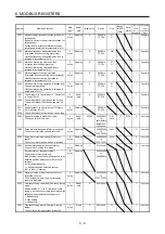
2B0C  Position within one-revolution (Within one-

revolution position) 
The position within one-revolution is returned. 

bytes 

Reading  80000000h 

to 

7FFFFFFFh 

pulse     2 

Possible 

2B0D  Multi-revolution counter (ABS counter) 

Returns the multi-revolution counter. 

bytes 

Reading  80000000h 

to 

7FFFFFFFh 

rev    2 

Possible 

2B0E  Load to motor inertia ratio (Load to motor inertia 

ratio) 
The load to motor inertia ratio is returned. 

bytes 

Reading   0000h 

to 

FFFFh 

0.01 

times 

  1 

Possible 

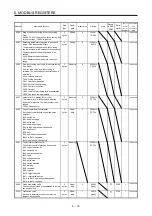
2B0F  Bus voltage (Bus voltage) 

The bus voltage is returned. 

bytes 

Reading   0000h 

to 

FFFFh 

V   1 

Possible 

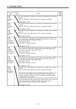
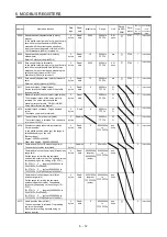
2B16  F/B cumulative value of A/B-phase output 

pulse (Cumulative encoder out pulses) 
The feedback cumulative value of A/B-phase 
output pulse is returned. 

bytes 

Read  

80000000h 

to 

7FFFFFFFh 

pulse     2 

Impossible 

2B25  Internal temperature of encoder (Internal 

temperature of encoder) 
The internal temperature of encoder is 
returned. 

bytes 

Reading   8000h 

to 

7FFFh 

°C    1 

Impossible 

2B26  Settling time (Settling time) 

The settling time is returned. 


bytes 

Reading   8000h 

to 

7FFFh 

ms    1 

Impossible 

2B27  Oscillation detection frequency (Oscillation 

detection frequency) 
The oscillation detection frequency is returned. 

bytes 

Reading   8000h 

to 

7FFFh 

Hz    1 

Impossible 

2B28  Number of tough drive operations (Number of 

tough drive operations) 
The number of tough drive operations is 
returned. 

bytes 

Reading   0000h 

to 

FFFFh 

times     1 

Impossible 

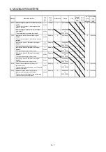
2B2A  Internal temperature of amplifier (Internal 

temperature of amplifier) 
The internal temperature of amplifier is 
returned. 

bytes 

Reading   8000h 

to 

7FFFh 

°C    1 

Impossible 

2B2D  Unit power consumption (Unit power 

consumption) 
The unit power consumption is returned. 

bytes 

Reading   8000h 

to 

7FFFh 

W   1 

Possible 

2B2E  Unit total power consumption (Unit total power 

consumption) 
The unit total power consumption is returned. 

bytes 

Reading  80000000h 

to 

7FFFFFFFh 

Wh    2 

Possible 

2B2F Current 

position 

(Current position) 

The current position is returned. 

bytes 

Reading  80000000h 

to 

7FFFFFFFh 


Possible 


Summary of Contents for MELSERVO-JE MR-JE-C

Page 1: ...ithout notice This Instruction Manual uses recycled paper MODEL MODEL CODE General Purpose AC Servo MR JE _C SERVO AMPLIFIER INSTRUCTION MANUAL Modbus TCP HEAD OFFICE TOKYO BLDG MARUNOUCHI TOKYO 100 8310 MODEL MR JE _C SERVO AMPLIFIER INSTRUCTION MANUAL Modbus TCP Ethernet Interface ...

Page 2: ... or severe injury CAUTION Indicates that incorrect handling may cause hazardous conditions resulting in medium or slight injury to personnel or may cause physical damage Note that the CAUTION level may lead to a serious consequence according to conditions Please follow the instructions of both levels because they are important to personnel safety What must not be done and what must be done are ind...

Page 3: ... a magnetic contactor is not connected continuous flow of a large current may cause smoke or a fire when the servo amplifier malfunctions Always connect a molded case circuit breaker or a fuse to each servo amplifier between the power supply and the power supply L1 L2 L3 of the servo amplifier in order to configure a circuit that shuts down the power supply on the side of the servo amplifier s pow...

Page 4: ... occur When you keep or use the equipment please fulfill the following environment Item Environment Ambient temperature Operation 0 C to 55 C non freezing Storage 20 C to 65 C non freezing Ambient humidity Operation 5 RH to 90 RH non condensing Storage Ambience Indoors no direct sunlight free from corrosive gas flammable gas oil mist dust and dirt Altitude 2000 m or less above sea level Contact yo...

Page 5: ...bing diode installed to the DC relay for control output should be fitted in the specified direction Otherwise the emergency stop and other protective circuits may not operate DOCOM Control output signal Servo amplifier RA For sink output interface 24 V DC DOCOM Control output signal 24 V DC Servo amplifier RA For source output interface When the cable is not tightened enough to the terminal block ...

Page 6: ...e correct combination Otherwise an electric shock fire injury etc may occur The electromagnetic brake on the servo motor is designed to hold the motor shaft and should not be used for ordinary braking For such reasons as incorrect wiring service life and mechanical structure e g where a ball screw and the servo motor are coupled via a timing belt the electromagnetic brake may not hold the motor sh...

Page 7: ...tenance inspection and parts replacement CAUTION Make sure that the emergency stop circuit operates properly such that an operation can be stopped immediately and a power is shut off by the emergency stop switch It is recommended that the servo amplifier be replaced every 10 years when it is used in general environment When using a servo amplifier whose power has not been turned on for a long time...

Page 8: ...is servo Ensure to prepare them to use the servo safely Relevant manuals Manual name Manual No MELSERVO MR JE _C Servo Amplifier Instruction Manual SH NA 030257ENG MELSERVO JE Servo Amplifier Instruction Manual Troubleshooting SH NA 030166ENG MELSERVO MR JE _C Servo Amplifier Instruction Manual Profile Mode SH NA 030254ENG MELSERVO HG KN HG SN Servo Motor Instruction Manual SH NA 030135ENG MELSERV...

Page 9: ...A 8 MEMO ...

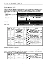
Page 10: ...st of communication related parameters 4 1 4 2 Detailed list of communication related parameters 4 3 5 MANUFACTURER FUNCTIONS 5 1 to 5 4 5 1 Stroke end 5 1 5 2 One touch tuning 5 2 5 3 Machine diagnosis function 5 4 5 4 Servo amplifier life diagnosis function 5 4 6 MODBUS REGISTERS 6 1 to 6 44 6 1 List of registers 6 1 6 2 Object library details objects in the 1000s 6 17 6 2 1 Writing command to E...

Page 11: ...oftware limit 607Dh 6 38 6 4 6 Polarity 607Eh 6 39 6 4 7 Degree 60F2h 6 39 6 4 8 Touch probe 60B8h to 60BBh 6 41 6 4 9 Touch probe function setting 60B8h 6 42 6 4 10 Touch probe function status 60B9h 6 43 6 4 11 Rising edge position of touch probe 60BAh 6 43 6 4 12 Falling edge position of touch probe 60BBh 6 43 6 4 13 Supported control mode 6502h 6 44 ...

Page 12: ...d between speed control and torque control Torque position control switch mode T P Using an input device control can be switched between torque control and position control Profile position mode pp The servo amplifier operates in the profile position mode MR JE _C Servo Amplifier Instruction Manual Profile Mode Profile velocity mode pv The servo amplifier operates in the profile velocity mode Prof...

Page 13: ...4 S pattern acceleration deceleration time constant Enables smooth acceleration and deceleration Set S pattern acceleration deceleration time constants with Pr PC03 As compared with linear acceleration deceleration the acceleration deceleration time will be longer for the S pattern acceleration deceleration time constants regardless of command speed Auto tuning Automatically adjusts the gain to op...

Page 14: ...r the Ethernet communication between a client master and servers slaves The dedicated message frames have functions for reading and writing data you can set the parameters of servo amplifiers and monitor it by using this function In the profile mode driving the servo motor is also possible Chapter 2 CC Link IE Field Network Basic CC Link IE Field Network Basic enables fixed cycle communication bet...

Page 15: ...ork address for both a client and servers Default value 192 168 3 0 Subnet mask Default value recommended 255 255 255 0 Message format Refer to section 2 Physical layer 1000BASE T Communication connector RJ45 1 port CN1 Communication cable CAT5e shielded twisted pair 4 pair straight cable Network topology Star Variable communication speed 100 Mbps Transmission speed between stations Max 100 m Wait...

Page 16: ...sponse Message Servo amplifier response time Note Query Message Response Message Note The servo amplifier response time differs depending on the command to send 2 2 Modbus TCP Communication Message Frame Query Messages sent from the client controller and Response Messages sent from the servers servo amplifiers are both sent in the following message frame format Messages are sent by using TCP IP Cl...

Page 17: ...d Server Client The value 0 is returned Length Field Message length 2 8 bits Client Server Set the byte length from Unit Identifier to Data Server Client The byte length from Unit Identifier to Data is returned Unit Identifier Unit identifier 8 bits Client Server The value is fixed to 255 If the server receives a value other than 255 the received value is discarded and no value is returned Server ...

Page 18: ...a points starting from the specified register address 1 Message frame Query Message Transaction Identifier Protocol Identifier Length Field Unit Identifier Function Starting Address No of Points H L H L 16 bits 0000h 0006h FFh 03h 8 bits 8 bits 8 bits 8 bits Message field Size Description Transaction Identifier Transaction identifier 16 bits Set any value Protocol Identifier Protocol identifier 16...

Page 19: ... is returned Data is read in order of H higher bits and L lower bits Data is read in order starting from the start address Note 1 Registers can be classified into two types registers that can be continuously accessed and particular registers that cannot be continuously accessed To read particular registers read only the target registers For the details on whether the target registers can be contin...

Page 20: ...Function Byte Count Data H L H L H L H L 16 bits 0000h 000Bh FFh 03h 08h 56h 78h 12h 34h 10h 00h 20h 00h The following shows the information in each Response Message Message field Description Transaction Identifier Transaction identifier Transaction Identifier received from the client controller is copied and returned Protocol Identifier Protocol identifier The value 0000h is returned Length Field...

Page 21: ...nction Sub function 16 bits Set 0000h When a value other than 0000h is set a communication error occurs Data Data 16 bits Set 2 byte length data Response Message Transaction Identifier Protocol Identifier Length Field Unit Identifier Function Sub Function Data H L H L 16 bits 0000h 0006h FFh 08h 00h 00h 8 bits 8 bits Message field Size Description Transaction Identifier Transaction identifier 16 b...

Page 22: ... 12h L 34h Response Message Transaction Identifier Protocol Identifier Length Field Unit Identifier Function Sub Function Data H L H L 16 bits 0000h 0006h FFh 08h 00h 00h 12h 34h The following shows the information in each Response Message Message field Description Transaction Identifier Transaction identifier Transaction Identifier received from the client controller is copied and returned Protoc...

Page 23: ...number Byte Count Byte count 16 bits Set the size of the data to write Data Writing data Note 16 bits n Set the data to write Response Message Transaction Identifier Protocol Identifier Length Field Unit Identifier Function Starting Address No of Points H L H L 16 bits 0000h 0006h FFh 10h 8 bits 8 bits 8 bits 8 bits Message field Size Description Transaction Identifier Transaction identifier 16 bi...

Page 24: ...is 2 Byte Count Byte count Set 04h This means that data of 4 frames is sent Data Writing data Set values in order starting from the start address Lower bit value of the register 2102h 0100h Higher bit value of the register 2102h 0000h Response Message Transaction Identifier Protocol Identifier Length Field Unit Identifier Function Starting Address No of Points H L H L 2 8 bits 0000h 0006h FFh 10h ...

Page 25: ...entifier received from the client controller is copied and returned Protocol Identifier Protocol identifier 16 bits The value 0000h is returned Length Field Message length 16 bits The byte length from Unit Identifier to Data is returned Unit Identifier Unit identifier 8 bits Unit Identifier received from the client controller is copied and returned Function Function field 8 bits A value obtained b...

Page 26: ...initial communication setting Make the initial communication settings in the following procedure Network setting IP address setting The initial value is 192 168 3 0 To change the initial value set it with either of the following 1 or 2 Refer to section 3 2 1 Identification number setting rotary switch SW1 SW2 2 Parameter Pr PN11 to Pr PN14 Subnet mask setting The initial value is 255 255 255 0 Set...

Page 27: ...etween 0 0 0 0 and 255 255 255 255 Set the IP address within the range Set the IP address with the identification number setting rotary switch SW1 SW2 on the display of the servo amplifier or MR Configurator2 When the IP address is changed with the identification number setting rotary switch SW1 SW2 change it before powering on the servo amplifier The IP address you set can be checked in the syste...

Page 28: ...alue of Pr PF25 Instantaneous power failure tough drive Detection time when instantaneous power failure tough drive selection is enabled in Pr PA20 In Modbus TCP communication the following parameter cannot be used Pr PN02 Communication error detection time No Symbol Name Initial value Unit PN01 For manufacturer setting 0h PN02 CERT Communication error detection time 1000 ms ms PN03 For manufactur...

Page 29: ... IP address 1 0 PN32 IPOA2 Operation specification IP address 2 0 PN33 IPOA3 Operation specification IP address 3 0 PN34 IPOA4 Operation specification IP address 4 0 PN35 IPOR3 Operation specification IP address 3 range specification 256 PN36 IPOR4 Operation specification IP address 4 range specification 256 PN37 For manufacturer setting 0000h PN38 0000h PN39 0000h PN40 0000h PN41 0000h PN42 0000h...

Page 30: ...00h 1st octet The setting value of Pr PN11 is used 2nd octet The setting value of Pr PN12 is used 3rd octet The setting value of Pr PN13 is used 4th octet The setting value of Pr PN14 is used 01h to FFh 1st octet The setting value of Pr PN11 is used 2nd octet The setting value of Pr PN12 is used 3rd octet The setting value of Pr PN13 is used 4th octet The setting value of the identification number...

Page 31: ...teway in decimal Set the default gateway assigned by the network administrator Setting range 0 to 255 192 PN20 DGW2 Default gateway setting 2 Set the 2nd octet of the default gateway in decimal Set the default gateway assigned by the network administrator Setting range 0 to 255 168 PN21 DGW3 Default gateway setting 3 Set the 3rd octet of the default gateway in decimal Set the default gateway assig...

Page 32: ...e network device allowed to be connected The range for the IP address of the network device allowed to be connected is between Pr PN26 and Pr PN29 Set a value in decimal Setting 256 will disable the function Setting range 0 to 256 256 PN30 IPAF4 IP address filter 4 range specification Set a value for the 4th octet range of the IP address of the network device allowed to be connected The range for ...

Page 33: ... GOT are within the range of the operation specification IP address When out of the range communication to the servo amplifier cannot be established Setting range 0 to 255 0 PN34 IPOA4 Operation specification IP address 4 Set the 4th octet of the IP address of the network device allowed to be connected in decimal When Pr PN31 to Pr PN34 are all set to 0 the function is disabled When the function i...

Page 34: ...P or LSN Servo motor speed 0 r min ON OFF Part of droop pulses No S pattern acceleration deceleration With S pattern acceleration deceleration LSP or LSN Travels for the droop pulses portion and stops the servo motor A difference will be generated between the command position and the current position Perform a home position return again Perform a return as follows when the stroke end is detected M...

Page 35: ...ting value changes to 100 at the completion Unit 2D52h Writing One touch tuning Stop 2 bytes 0 Writing 1EA5h stops one touch tuning Writing a value other than 1EA5h sets 0609 0030h Value range of parameter exceeded in SDO Abort Code 2D53h Writing One touch tuning Clear 2 bytes 0 The parameter changed in one touch tuning can be returned to the value before the change 0000h Restores the initial valu...

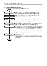
Page 36: ... perform in One touch tuning mode 2D50h during servo motor driving to perform one touch tuning Gains and filters will be adjusted automatically During one touch tuning the progress can be checked with One touch tuning status 2D51h Check whether one touch tuning is completed normally with One touch tuning Error Code 2D54h When the one touch tuning is completed normally the parameters will be set au...

Page 37: ...iction at reverse rotation torque is displayed in increments of 0 1 2C24h Reading Dynamic friction torque at reverse rotation at rated speed 2 bytes Kinetic friction at reverse rotation torque at the rated speed is displayed in increments of 0 1 2C25h Reading Oscillation frequency during motor stop 2 bytes Vibration frequency during stop servo lock is displayed in increments of 1 Hz 2C26h Reading ...

Page 38: ...d with the command No parameter is being saved Bit 1 0 The parameter is not automatically saved 4 bytes Read write 00000001h 1011 Restoring default EEP ROM parameters Restore default parameters The number of entries is returned 1 bytes Reading 1 01h fixed 3 Impossible Restoring all default parameters Restore all default parameters The parameter of the servo amplifier can be rewritten with the fact...

Page 39: ...arameters Pr PT_ _ can be obtained and set For details refer to MR JE _C Servo Amplifier Instruction Manual Profile Mode 4 bytes Read write PT01 to PT80 2 Possible 2581 to 25B0 PN01 to PN48 The values of the network setting parameters Pr PN_ _ can be obtained and set Refer to chapter 5 for details 4 bytes Read write PN01 to PN48 2 Possible 2A00 to 2A0F Alarm history 0 to Alarm history 15 Alarm his...

Page 40: ...manufacturer setting 08 Parameter for manufacturer setting 09 Parameter for manufacturer setting 0A Parameter for manufacturer setting 0B Parameter for manufacturer setting 0C Pr PT _ _ 0E Pr PN _ _ 2 bytes Reading 0 0000h to FFFFh 2A46 Alarm reset Reset alarm Writing the value 1EA5h resets an alarm Any value other than 1EA5h is ignored 2 bytes Writing 0 0000h to FFFFh 1 Impossible 2A60 SDO abort ...

Page 41: ...n counter ABS counter Returns the multi revolution counter 4 bytes Reading 80000000h to 7FFFFFFFh rev 2 Possible 2B0E Load to motor inertia ratio Load to motor inertia ratio The load to motor inertia ratio is returned 2 bytes Reading 0000h to FFFFh 0 01 times 1 Possible 2B0F Bus voltage Bus voltage The bus voltage is returned 2 bytes Reading 0000h to FFFFh V 1 Possible 2B16 F B cumulative value of...

Page 42: ...se s 2 Possible 2B86 Analog speed command voltage at alarm occurrence Alarm Monitor 6 Analog speed command voltage The analog speed command voltage at alarm occurrence is returned 2 bytes Reading 8000h to 7FFFh V 1 Possible 2B87 Analog torque limit voltage Analog torque command voltage at alarm occurrence Alarm Monitor 7 Analog torque limit voltage Analog torque command voltage The analog torque l...

Page 43: ...currence Alarm Monitor 40 Number of tough drive operations The number of tough drive operations at alarm occurrence is returned 2 bytes Reading 0000h to FFFFh times 1 Possible 2BAA Internal temperature of amplifier at alarm occurrence Alarm Monitor 42 Internal temperature of amplifier The internal temperature of amplifier at alarm occurrence is returned 2 bytes Reading 8000h to 7FFFh C 1 Possible ...

Page 44: ...al display1 The input device status 1 is returned 4 bytes Reading 00000000h to FFFFFFFFh Input device status 2 External Input signal display2 The input device status 2 is returned 4 bytes Reading 00000000h to FFFFFFFFh Input device status 3 External Input signal display3 The input device status 3 is returned 4 bytes Reading 00000000h to FFFFFFFFh Input device status 4 External Input signal display...

Page 45: ...otor speed may too slow for friction estimation 4 Warning The change in the servo motor speed may be small for friction estimation 5 Warning The acceleration deceleration time constants may be too short for friction estimation 6 Warning The operation time may not be enough When warning conditions for 2 to 6 are met at the same time the smaller number is returned When an estimation is completed eve...

Page 46: ...000h to FFFFh 1 Possible 2D11 to 2D1A Control output 1 to Control output 10 Status DO 1 to Status DO 10 The on off status of output device can be read 2 bytes Reading 0000h to FFFFh 1 Possible 2D20 Speed limit value Velocity limit value The speed limit value is set 4 bytes Read write 50000 00000000h to permissible instantane ous speed 0 01 r min PT52 2 Impossible 2D28 Servo motor rated speed Motor...

Page 47: ...0000h to C00Fh 1 Impossible 603F Latest error No display Error code The latest error No that occurred after the power on is returned The error number is as follows 1000h Generic error 2 bytes Reading 0 0000h to FFFFh 1 Impossible 6040 Control command Controlword Set control commands to control the servo amplifier Bit 0 switch on Bit 1 enable voltage Bit 2 quick stop Bit 3 enable operation Bit 4 to...

Page 48: ...le 6065 Error excessive width Following error window In the profile position mode pp when the time set with Following error time out 6066h has elapsed with the number of droop pulses exceeding the setting value of this object bit 13 of Statusword 6041h is turned on When FFFFFFFFh is set Bit 13 of Statusword 6041h is always off 4 bytes Read write 12582912 00000000h to FFFFFFFFh pos units PC75 PC76 ...

Page 49: ...sible 6074 Internal torque command Torque demand value The torque command is returned 2 bytes Read 0 8000h to 7FFFh 0 1 1 Impossible 6077 Current torque Torque actual value The current torque is returned The read data is in the unit of 0 1 2 bytes Reading 8000h to 7FFFh 0 1 1 Impossible 607A Position command absolute incremental Target position In the profile position mode pp the range is limited ...

Page 50: ...rite 00h 00h to FFh PA14 PC29 1 Impossible 607F Maximum speed command Max profile velocity Set the maximum speed command for the profile position mode pp and profile velocity mode pv When a value exceeding this object is set to Target velocity 60FFh or Profile velocity 6081h the speed is limited with the value of this object 4 bytes Read write 2000000 00000000h to 001E8480h 2000000 0 01 r min PT51...

Page 51: ...F Encoder information Position encoder resolution The number of entries is returned 1 bytes Reading 2 02h fixed pulse rev 5 Impossible Encoder resolution Encoder increments The encoder resolution is returned 4 bytes Read write 00000000h to FFFFFFFFh pulse Number of revolutions of the servo motor fixed to 1 rev Motor revolutions The fixed value 1 is returned 4 bytes Read write 1 00000001h to 000000...

Page 52: ...less Bit 24 to Bit 31 Prefix FD means milli and 00 means none 4 bytes Read write FD410000h degree 00000000h pulse 00000000h to FFFFFFFFh 2 Impossible 60A9 SI unit velocity SI unit velocity The SI unit velocity is returned FEB44700h 0 01 r min 4 bytes Read write FEB44700h FEB44700h 0 01 r min 2 Impossible 60B8 Touch probe function setting Touch probe function Set the command for the touch probe fun...

Page 53: ...ption Specify the operation of the rotation axis during pp and pt 00 The servo motor rotates to the target position in a direction specified with a sign of the position data 01 The servo motor rotates in the address decreasing direction regardless of the sign of the position data 10 The servo motor rotates in the address increasing direction regardless of the sign of the position data 11 The servo...

Page 54: ...The value saved in the EEP ROM is set to the object at the next power on Servo parameters can also be modified through the object library However the new setting is not automatically written to the EEP ROM To write the new setting use the writing command to EEP ROM Store Parameters 1010h Executing the writing command to EEP ROM Store Parameters 1010h takes about a maximum of 10 s because all param...

Page 55: ...an 65766173h and 00000000h to each item results in an error Item Setting value Write to EEP ROM Parameter Number of entries Number of entries 01h Saving all parameters Save all parameters 00000000h Disabled 65766173h save Enabled Other than above Error 6 2 2 Restore default EEP ROM parameters 1011h Address Name Data type Read write No of Points No of Registers Continuous read continuous write 1011...

Page 56: ...tes Reading The ON OFF state of the external input pins input to the servo amplifier can be read 1 Usage Read the ON OFF state of external input pins using this object At this time 02h is returned to Number of entries External Input pin display1 displays the input pin status of the MR JE _C servo amplifier The following table shows the details When the input of the target pin is on 1 is returned W...

Page 57: ...When the output of the target pin is on 1 is returned When the output of the target pin is off 0 is returned The values in the areas marked with diagonal lines are indefinite Bit CN3 connector pin Bit CN3 connector pin Bit CN3 connector pin Bit CN3 connector pin 0 14 8 16 24 1 22 9 17 25 2 16 10 18 26 3 11 19 27 4 12 20 28 5 15 13 21 29 6 14 22 30 7 15 23 31 6 3 3 Input device status 2C12h Address...

Page 58: ...us 4 0 SON Servo on 1 LSP Forward rotation stroke end 2 LSN Reverse rotation stroke end 3 TL External torque limit selection 4 TL1 Internal torque limit selection 5 PC Proportional control 6 RES Reset 7 CR Clear 8 SP1 Speed selection 1 9 SP2 Speed selection 2 DOG Proximity dog 10 SP3 Speed selection 3 11 ST1 RS2 Forward rotation start reverse rotation selection 12 ST2 RS1 Reverse rotation start fo...

Page 59: ...ue control mode C_EM2 functions the same as C_EM1 C_EM1 This device can be used by setting 0 _ _ _ in Pr PA04 When C_EM1 is turned on the base circuit shuts off and the dynamic brake operates to decelerate the servo motor to a stop Turn C_EM1 off in the forced stop state to reset that state 1 The value at reading is undefined Set 0 when writing 2 3 4 C_CDP Gain switching Turn on C_CDP to use the v...

Page 60: ...ue limit selection at the same time to make the torque less than the rated by TLA Analog torque limit Do not use C_PC in the torque control When C_PC is used in the torque control operation may be performed at a speed exceeding the speed limit value 9 The value at reading is undefined Set 0 when writing 10 11 12 13 14 15 C_ORST Operation alarm reset Turn on C_ORST from off to reset AL F4 Positioni...

Page 61: ... 11 12 13 14 15 5 Bit definition of control DI5 Bit Symbol Description 0 The value at reading is undefined Set 0 when writing 1 2 3 4 5 6 7 8 9 10 11 C_DOG Proximity dog input When C_DOG is turned on a proximity dog will be detected The polarity for dog detection can be changed with Pr PT29 12 The value at reading is undefined Set 0 when writing 13 14 15 ...

Page 62: ...ing 1 2 3 4 5 6 7 8 9 10 11 12 13 14 15 7 Bit definition of control DI7 Bit Symbol Description 0 The value at reading is undefined Set 0 when writing 1 2 3 4 5 6 7 8 9 10 11 12 13 14 15 8 Bit definition of control DI8 Bit Symbol Description 0 The value at reading is undefined Set 0 when writing 1 2 3 4 5 6 7 8 9 10 11 12 13 14 15 ...

Page 63: ...t Symbol Description 0 The value at reading is undefined Set 0 when writing 1 2 3 4 5 6 7 8 9 10 11 12 13 14 15 10 Bit definition of control DI10 Bit Symbol Description 0 The value at reading is undefined Set 0 when writing 1 2 3 4 5 6 7 8 9 10 11 12 13 14 15 ...

Page 64: ...netic brake interlock When a servo off status or alarm occurs S_MBR will turn off 4 S_CDPS Variable gain selection S_CDPS turns on during gain switching 5 The value at reading is undefined 6 7 S_TL Analog torque limit selection When TL External torque limit selection is turned on S_TL turns on 8 S_TL1 Torque limit selection When C_TL1 or TL1 Internal torque limit selection is turned on S_TL1 turns...

Page 65: ...tes normally S_ZP2 turns on S_ZP2 is always on unless the home position is erased In the incremental system it turns off with one of the following conditions 1 AL 69 Command error occurs 2 Home position return is not being executed 3 Home position return is in progress If a home position return completes once in the absolute position detection system S_ZP2 is always on However it will be off with ...

Page 66: ...d stop deceleration 10 The value at reading is undefined 11 S_MTTR Transition to tough drive mode in process When a tough drive is Enabled in Pr PA20 activating the instantaneous power failure tough drive will turn on S_MTTR 12 The value at reading is undefined 13 14 15 4 Bit definition of Status DO 4 Bit Symbol Description 0 The value at reading is undefined 1 2 3 4 5 6 7 8 9 10 11 12 13 14 15 ...

Page 67: ...on of Status DO 5 Bit Symbol Description 0 The value at reading is undefined 1 2 3 4 5 6 7 8 9 10 11 12 13 14 15 6 Bit definition of Status DO 6 Bit Symbol Description 0 The value at reading is undefined 1 2 3 4 5 6 7 8 9 10 11 12 13 14 15 ...

Page 68: ...on of Status DO 7 Bit Symbol Description 0 The value at reading is undefined 1 2 3 4 5 6 7 8 9 10 11 12 13 14 15 8 Bit definition of Status DO 8 Bit Symbol Description 0 The value at reading is undefined 1 2 3 4 5 6 7 8 9 10 11 12 13 14 15 ...

Page 69: ...n of Status DO 9 Bit Symbol Description 0 The value at reading is undefined 1 2 3 4 5 6 7 8 9 10 11 12 13 14 15 10 Bit definition of Status DO 10 Bit Symbol Description 0 The value at reading is undefined 1 2 3 4 5 6 7 8 9 10 11 12 13 14 15 ...

Page 70: ...s to a register 0601 0001h Attempt to read a write only register 0601 0002h Attempt to write a read only register 0602 0000h Register does not exist in the Modbus resisters 0604 0041h Resister cannot be mapped to the PDO 0604 0042h The number and length of the resisters to be mapped would exceed PDO length 0607 0010h Data type does not match length of service parameter does not match 0609 0011h El...

Page 71: ... 2C12h is accessed successfully 2C120004h is read from the access log 1 6 3 8 Access log 2 2A65h Address Name Data type Read write No of Points No of Registers Continuous read continuous write 2A65h Access log 2 Access log 2 2 bytes Read 1 Impossible The access log 2 can be read 1 Usage Read the access log 2 using this register The access log 2 displays the number of addresses that were accessed s...

Page 72: ...ved Note 2 9 Reserved Note 2 10 Target reached Note 1 11 Internal Limit Active 12 to 13 Operation Mode Specific Note 1 14 to 15 Reserved Note 2 Note 1 The description changes depending on the control mode 2 The value at reading is undefined The following table lists the servo amplifier statuses that can be read with bit 0 to bit 7 Bit 7 Bit 6 Bit 5 Bit 4 Bit 3 Bit 2 Bit 1 Bit 0 Status 0 0 0 0 0 No...

Page 73: ...le shows the supported methods and the operations Setting value Description 1 For manufacturer setting 2 In the profile mode pp pv and homing mode hm the servo motor decelerates to a stop with Quick stop deceleration 6085h and the state shifts to the Switch On Disabled state The new setting of Quick stop deceleration is reflected at all times In the profile torque mode tq the state immediately shi...

Page 74: ...eration 6084h is reflected when New set point Bit 4 of Controlword 6040h is set to 1 Profile velocity mode pv The servo motor decelerates to a stop according to Profile deceleration 6084h The operation restarts after the servo motor decelerates to a stop The new setting of Profile deceleration 6084h is reflected at all times Profile torque mode tq Torque demand value 6074h becomes 0 with the amoun...

Page 75: ... write 607Dh Software limit Software Position Limit Number of entries Number of entries 1 bytes Reading 5 Impossible Min Position Limit Stroke limit 4 bytes Read write Max Position Limit Stroke limit 4 bytes The current software limit setting can be read At this time 02h is returned to Number of entries The stroke limit value in the reverse direction is returned to Min Position Limit stroke limit ...

Page 76: ...rsed when this bit is turned on Select a rotation direction by setting bit 5 to bit 7 in combination 6 4 7 Degree 60F2h Address Name Data type Read write No of Points No of Registers Continuous read continuous write 60F2h Profile position mode setting Positioning option code 2 bytes Read write 1 Impossible Selecting degree _ 2 _ _ in Position data unit of Pr PT01 allows for positioning with module...

Page 77: ... position to the target position in the shorter direction If the distances from the current position to the target position are the same for CCW and CW the servo motor rotates in the CCW direction The following shows the operation patterns corresponding to the settings of Positioning option code 60F2h a When POL is disabled Pr PA14 0 150 210 50 330 360 0 150 210 50 330 360 0 150 210 50 330 360 0 1...

Page 78: ...ad with the touch probe position positive value 60BAh and the touch probe position negative value 60BBh For details of each object refer to sections 6 4 9 to 6 4 12 2 Usage The following explains for latching the current position at the rising edge of TPR1 Touch probe 1 a Set 0013h to the touch probe function setting Touch probe function 60B8h to store data at rising edge of TPR1 Touch probe 1 b A...

Page 79: ...0 Latch function disabled 1 Latch function enabled 1 0 Latch with the first trigger 1 Continuously latch with trigger inputs 2 The value at reading is undefined Set 0 when writing 3 4 0 Stop sampling at the rising edge of touch probe 1 Start sampling at the rising edge of touch probe 5 0 Stop sampling at the falling edge of touch probe 1 Start sampling at the falling edge of touch probe 6 to 15 Th...

Page 80: ...bled and 1 enabled With bit 1 if the data is latched at the rising edge of the touch probe can be checked Latched data can be read when this bit is set to 1 When this bit turns on it remains on until bit 4 of the touch probe setting 60B8h is set to 0 With bit 2 if the data is latched at the falling edge of the touch probe can be checked Latched data can be read when this bit is set to 1 When this ...

Page 81: ...h Supported control mode Supported Drive Modes 4 bytes Reading 2 Impossible The supported control mode can be read The returned value is 0000002Dh The following table shows the details Bit Supported Modes Defined value 0 Profile position mode pp 1 Supported 2 Profile velocity mode pv 1 Supported 3 Profile torque mode tq 1 Supported 5 Homing mode hm 1 Supported ...

Page 82: ...ition This manual confers no industrial property rights or any rights of any other kind nor does it confer any patent licenses Mitsubishi Electric Corporation cannot be held responsible for any problems involving industrial property rights which may occur as a result of using the contents noted in this manual 2017 MITSUBISHI ELECTRIC CORPORATION ...

Page 83: ...MEMO ...
Page 84: ...d trademarks or trademarks of Microsoft Corporation in the United States Japan and or other countries Intel Pentium and Celeron are trademarks of Intel Corporation in the United States and or other countries Ethernet is a registered trademark of Fuji Xerox Co Ltd in Japan All other product names and company names are trademarks or registered trademarks of their respective companies ...

Page 85: ...ct from our company viii any other failures which we are not responsible for or which you acknowledge we are not responsible for 2 Term of warranty after the stop of production 1 We may accept the repair at charge for another seven 7 years after the production of the product is discontinued The announcement of the stop of production for each model can be seen in our Sales and Service etc 2 Please ...

Page 86: ...ithout notice This Instruction Manual uses recycled paper MODEL MODEL CODE General Purpose AC Servo MR JE _C SERVO AMPLIFIER INSTRUCTION MANUAL Modbus TCP HEAD OFFICE TOKYO BLDG MARUNOUCHI TOKYO 100 8310 MODEL MR JE _C SERVO AMPLIFIER INSTRUCTION MANUAL Modbus TCP Ethernet Interface ...

Reviews: