background image


32 


RsXs(?)

  Serial resistance and serial reactance measurement 

mode setting or querying command.


RpXp(?)

 Parallel resistance and parallel reactance 

measurement mode setting or querying command.


ZTD(?)

  Impedance and angle (Deg) measurement mode 

setting or querying command.


ZTR(?)

  Impedance and angle (Rad) measurement mode 

setting or querying command.


Example: 
 CPD 

(

set to Cp-D measurement mode) 

 
 CPD? 
 0.22724 

0.12840 

(

return value


 DCR? 
 5.1029 

(

return value

 
*IDN? 

Queries and identifies the MT4080. This command is used to 
identify the basic information of MT4080. The return value has 
four fields separated by comma (,). The total length will not greater 
than 100 characters. The four fields are: 
1. Manufacturer Name 
2. Model Number 
3. Serial Number 
4. Firmware Number 
Example: 

MOTECH,MT4080A,123456789,4.096 


Summary of Contents for MT 4080

Page 1: ...MT 4080 LCR METER OPERATING MANUAL...

Page 2: ...ration 23 2 2 4 Display Speed 24 2 2 5 Relative Mode 24 2 2 6 Range Hold 24 2 2 7 DC Resistance Measurement 25 2 2 8 AC Impedance Measurement 25 2 2 9 Capacitance Measurement 25 2 2 10 Inductance Meas...

Page 3: ...1KHz 10KHz or 100KHz MT4080A only may be selected on all applicable ranges The test voltages of 50mVrms 0 25Vrms 1Vrms or 1VDC DCR only may also be selected on all applicable ranges The dual display...

Page 4: ...witches circuit board foils etc The key features are as following Test condition 1 Frequency 100Hz 120Hz 1KHz 10KHz 100KHz MT4080A only 2 Level 1Vrms 0 25Vrms 50mVrms 1VDC DCR only Measurement Paramet...

Page 5: ...e DC impedance and AC impedance The common digital multi meter can only measure the DC impedance but the MT4080 can do both It is a very important issue to understand the impedance parameters of the e...

Page 6: ...pacitive XC It can be defined as follows Also there are quality factor Q and the dissipation factor D that need to be discussed For component the quality factor serves as a measure of the reactance pu...

Page 7: ...io of the stored energy reactance and the dissipated energy resistance Q is generally used for inductors and D for capacitors There are two types of the circuit mode One is series mode the other is pa...

Page 8: ...0 H to 9999 H C 0 000 pF to 9999 F DCR 0 000 to 9999 M ESR 0 000 to 9999 D 0 000 to 9999 Q 0 000 to 9999 180 0 to 180 0 Figure 1 2 Real and imaginary components are serial s s jX R Z Rs jXs Real and i...

Page 9: ...1 100KHz 4080A NA 5 1 2 1 0 4 1 2 1 5 1 Note 1 The accuracy applies when the test level is set to 1Vrms 2 Ae multiplies 1 25 when the test level is set to 250mVrms 3 Ae multiplies 1 50 when the test...

Page 10: ...0Hz 2 1 X 1 1 0 5 1 0 2 1 0 5 1 1 1 X 7 957 pF 15 91 pF 15 91 pF 159 1 pF 159 1 pF 1 591 nF 1 591 nF 15 91 uF 15 91 uF 159 1 uF 159 1 uF 1 591 mF 1KHz 2 1 X 1 1 0 5 1 0 2 1 0 5 1 1 1 X 0 795 pF 1 591...

Page 11: ...2 1 X 1 1 0 5 1 0 2 1 0 5 1 1 1 X 3 183 KH 1 591 KH 1 591 KH 159 1 H 159 1 H 15 91 H 15 91 H 1 591 mH 1 591 mH 159 1 uH 159 1 uH 15 91 uH 1KHz 2 1 X 1 1 0 5 1 0 2 1 0 5 1 1 1 X 318 3 H 159 1 H 159 1 H...

Page 12: ...Hz 0 020 0 010 10KHz 0 050 0 020 0 005 0 002 0 005 0 010 100KHz 4080A NA 0 050 0 020 0 004 0 020 0 050 Accuracy Zx Freq 20M 10M 10M 1M 1M 100K 100K 10 10 1 1 0 1 100Hz 120Hz 1KHz 1 046 0 523 10KHz 2 6...

Page 13: ...x Measured Capacitance Value F Zx Measured Impedance Value Accuracy applies when Dx measured D value 0 1 When Dx 0 1 multiply CAe by 2 1 Dx Example Test Condition Frequency 1KHz Level 1Vrms Speed Slow...

Page 14: ...sured Impedance Value Accuracy applies when Dx measured D value 0 1 When Dx 0 1 multiply LAe by 2 1 Dx Example Test Condition Frequency 1KHz Level 1Vrms Speed Slow DUT 1mH Then 283 6 10 10 2 2 3 3 Lx...

Page 15: ...ance Value H Cx Measured Capacitance Value F Accuracy applies when Dx measured D value 0 1 Example Test Condition Frequency 1KHz Level 1Vrms Speed Slow DUT 100nF Then 1590 10 100 10 2 1 2 1 9 3 Cx f Z...

Page 16: ...Dx by 1 Dx Example Test Condition Frequency 1KHz Level 1Vrms Speed Slow DUT 100nF Then 1590 10 100 10 2 1 2 1 9 3 Cx f Zx Refer to the accuracy table get CAe 0 2 002 0 100 Ae DAe Q Accuracy De Qx De...

Page 17: ...xample Test Condition Frequency 1KHz Level 1Vrms Speed Slow DUT 1mH Then 283 6 10 10 2 2 3 3 Lx f Zx Refer to the accuracy table get LAe 0 5 005 0 100 Ae De If measured Qx 20 Then 1 0 1 2 1 2 m m De Q...

Page 18: ...low DUT 100nF Then 1590 10 100 10 2 1 2 1 9 3 Cx f Zx Refer to the accuracy table get ZAe 0 2 deg 115 0 100 2 0 180 100 Ae 180 Ae Testing Signal Level Accuracy 5 Frequency Accuracy 0 1 Output Impedanc...

Page 19: ...and can be changed Generally a 1kHz test signal is used to measure capacitors that are 0 01uF or smaller and a 120Hz test signal is used for capacitors that are 10uF or larger Typically a 1 kHz test s...

Page 20: ...autoranging and manual ranging is a very convenient way to gain the advantage of both modes Starting in the autoranging mode insert or connect the inductor to be measured The instrument quickly steps...

Page 21: ...mode may be more appropriate For iron core inductors operating at higher frequencies where hysteresis and eddy currents become significant measurement in the parallel equivalent mode is preferred 1 4...

Page 22: ...icator 5 Model Number 6 Power Switch 7 Relative Key 8 Measurement Level Key 9 Open Short Calibration Key 10 Measurement Frequency Key 11 Display Update Speed Key 12 D Q ESR Function Key 13 Range Hold...

Page 23: ...o change the batteries 1 Remove the battery hatch by unscrewing the screw of the battery compartment 2 Take out the old batteries and insert the new batteries into the battery compartment Please watch...

Page 24: ...lled Battery Select Switch If the Ni Mh or Ni Cd rechargeable batteries are installed in MT4080 set the Battery Select Switch to Ni Mh position The Ni Mh or Ni Cd batteries can be recharged when the i...

Page 25: ...ement terminals at the open status Press the CAL key shortly no more than two second the LCD will display This calibration takes about 10 seconds After it is finished the MT4080 will beep to show that...

Page 26: ...alue reading Approximately 5 seconds in Fast Mode to get a stable reading Then press the Relative key the primary display will reset to zero Remove the standard value component and insert the unknown...

Page 27: ...Z DCR key to make the Z measurement The LCD display The testing level and frequency can by selected by pressing the Level key and Frequency key respectively 2 2 9 Capacitance Measurement To measure th...

Page 28: ...Select the L C Z DCR key to Ls or Lp mode for measuring the inductance in serial mode or parallel mode If the serial mode Ls is selected the D Q and ESR can be shown on the secondary display If the p...

Page 29: ...27 2 3 Accessory Operation Follow the figures below to attach the test probes for making measurement Shorting Bar TL08A SMD Test Probe...

Page 30: ...28 H H P C C L L P TL08B 4 Wire Test Clip TL08C Kelvin Clip...

Page 31: ...Transmission Mode Half Duplex Baud Rate 9600 Parity Bit None Data Bits 8 Stop Bit 1 Handshake None In this mode the keyboard and LCD will be locked And the MT4080 measurement is controlled by the exte...

Page 32: ...0 05V 5 0e1mV 4 The question mark at the end of COMMAND means a query or measure back command For example CpD sets the measurement mode to Cp and D CpD sets the measurement mode to Cp and D as well as...

Page 33: ...ng or querying command CsQ Serial capacitance and quality factor measurement mode setting or querying command CsD Serial capacitance and dissipation factor measurement mode setting or querying command...

Page 34: ...ad measurement mode setting or querying command Example CPD set to Cp D measurement mode CPD 0 22724 0 12840 return value DCR 5 1029 return value IDN Queries and identifies the MT4080 This command is...

Page 35: ...de PARAMETER ON ASCII string OFF Numerical code Example ASC ON FREQ 1KHz return value ASC OFF FREQ 2 return value CORR OPEN Performs the open calibration This command sets the MT4080 to do the open ca...

Page 36: ...AMETER ASCII string Numerical code 100Hz 0 120Hz 1 1KHz 2 10KHz 3 100KHz 4 Example FREQ 100KHz FREQ Returns the current measurement frequency setting Example ASC ON FREQ 1KHz return value ASC OFF FREQ...

Page 37: ...turn value ASC OFF LEV 1 return value MODE Queries the measurement mode Six fields will be returned 1 Frequency 2 Level 3 Speed 4 Measurement mode 5 Unit of primary display 6 Unit of secondary display...

Page 38: ...p uF Ohm return value RANG PARAMETER Sets queries the measurement unit RANG PARAMETER Sets the measurement unit according to the parameter There is no return value PARAMETER ASCII string Numerical cod...

Page 39: ...ement value This command will perform a measurement according to the current measurement mode and return the measured value Example CPD READ 0 22724 0 12840 return value DCR READ 5 1029 return value T...

Page 40: ...Sets the measurement speed according to the parameter There is no return value PARAMETER ASCII string Numerical code SLOW 0 FAST 1 Example SPEED FAST SPEED Returns the current measurement speed settin...

Page 41: ...2 Terminal is the easiest way to connect the DUT but it contents many errors that are the inductor and resistor as well as the parasitic capacitor of the test leads Figure 3 1 Due to these errors in m...

Page 42: ...able should connect to guard of the instrument to increase the measurement range up to 10M DUT V A d 2T CONNECTION WITH SHILDING HCUR HPOT DUT b BLOCK DIAGRAM DUT V A Co Ro Lo Ro Lo Co doesn t effect...

Page 43: ...uctance can t be eliminated HCUR HPOT DUT b BLOCK DIAGRAM DUT V A a CONNECTION c TYPICAL IMPEDANCE MEASUREMENT RANGE 4T 1m 10m 100m 1 10 1K 10K 100K 1M 100 10M LPOT LCUR Figure 3 3 5 Terminal 5T 5 Ter...

Page 44: ...Terminal Path 4TP 4 Terminal Path connection solves the problem that caused by the test lead inductance 4TP uses four coaxial cables to isolate the current path and the voltage sense cable Figure 3 5...

Page 45: ...TH SHILDING Figure 3 5 Eliminating the Effect of the Parasitic Capacitor When measuring the high impedance component i e low capacitor the parasitic capacitor becomes an important issue Figure 3 6 In...

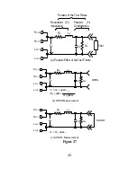
Page 46: ...short compensation need to be used to reduce the parasitic effect of the test fixture The parasitic effect of the test fixture can be treated like the simple passive components in figure 3 7 a When t...

Page 47: ...Parastic Conductance Yo Parastic of the Test Fixture a Parastic Effect of the Test Fixture HCUR HPOT LCUR LPOT Co Rs Ls Go b OPEN Measurement Yo OPEN Yo Go j sCo 1 Rs j s Go j sCo HCUR HPOT LCUR LPOT...

Page 48: ...e value to decide what mode to be used Capacitor The impedance and capacitance in the capacitor are negatively proportional Therefore the large capacitor means the low impedance the small capacitor me...

Page 49: ...shows the equivalent circuit of inductor If the inductor is small the Rs is more important than the Rp If the inductor is large the Rp should be taking care of So uses series mode to measure low induc...

Page 50: ...48 Figure 3 9 Small inductor Low impedance RP L RS Large inductor High impedance Effect No Effect RP L RS No Effect Effect...

Page 51: ...in but not limited to cracked or broken case or parts or to units damaged by excessive heat Except upon initial purchase this warranty does not cover finish or appearance items nor does it cover items...

Page 52: ...n lieu of all other agreements and warranties general or special express or implied no representative or person is authorized to assume for us any other liability in connection with the sale or use of...

Page 53: ...y precautions must be observed during all phases of operation service and repair of this instrument Failure to comply with these precautions or with specific warnings elsewhere in this manual violates...

Page 54: ...Because of the danger of introducing additional hazards do not install substitute parts or perform any unauthorized modification to the instrument Return the instrument to a qualified dealer for servi...

Page 55: ...ZOM 408MT 1...

Reviews: