SD34002g_e.doc / Sep-13
Page 52 / 60
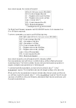
Upon correct request, the counter will respond:
STX C1 C2 x x x x x x x ETX BCC
STX = Control character (Hex 02)
C1 = Register code to read, High Byte
C2 = Register code to read, Low Byte
xxxxx = Counter data *)
ETX = Control character (Hex 03)
BCC = Block check character
*) Leading zeros will not be transmitted
The Block-Check-Character represents the EXCLUSIVE-OR function of all characters from
C1 to ETX (both comprised).
To write to a parameter, you have to send the following string:
EOT AD1 AD2 STX C1 C2 x x x x x x x ETX BCC
EOT = Control character (Hex 04)
AD1 = Unit address, High Byte
AD2 = Unit address, Low Byte
STX = Control character (Hex 02)
C1 = Register code to write, High Byte
C2 = Register code to write, Low Byte
xxxxx = Value of the parameter
ETX = Control character (Hex 03)
BCC = Block check character
Upon correct receipt the unit will respond by ACK, otherwise by NAK.
Every new parameter sent will first go to a buffer memory, without affecting the actual
measuring process. This function enables the user, during normal measuring operation, to
prepare a complete new parameter set in the background.
To activate transmitted parameters, you must write the numeric value “1” to the “
Activate Data“ register. This immediately activates all changed settings at the same time.
Where you like the new parameters to remain valid also after the next power up of the unit,
you still have to write the numeric value “1” to the „Store EEProm“ register. This will store all
new data to the EEProm of the unit. Otherwise, after power down the unit would return with
the previous parameter set.


