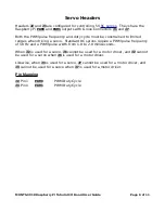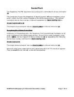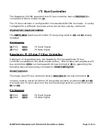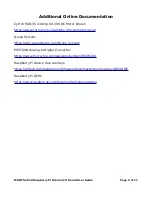
Button
The momentary switch button
SW1
is connected to Raspberry Pi
GPIO6
. When the
button is pressed, reading
GPIO6
yields a 1/High/True value. When the button is
released, reading
GPIO6
yields a 0/Low/False value.
LED
Light Emitting Diode (LED)
D1
is connected to Raspberry Pi
GPIO26
. Writing a
1/High/True value to
GPIO26
turns on the LED and writing a 0/Low/False value to
GPIO26
turns off the LED.
Analog Inputs
An
Analog to Digital Converter provides 4 analog inputs that are
connected to Grove Connectors
J10
and
J11
. Each analog input channel has a
resolution of 12 bits (values 0 to 4095 inclusive) and a full scale range of 0.0 to
3.3V. The absolute accuracy of the analog inputs will depend on the accuracy of
the Raspberry Pi 3.3V regulator, which is connected to the MCP3204 voltage
reference input.
The following device tree overlay command must be appended to
/boot/config.txt
to enable Linux kernel support for the MCP3204:
dtoverlay=anyspi,spi0-1,dev="microchip,mcp3204",speed=1000000
Pin Mapping
J10
Pin 1
AIN2
/sys/bus/iio/devices/iio:device0/in_voltage2_raw
J10
Pin 2
AIN3
/sys/bus/iio/devices/iio:device0/in_voltage3_raw
J11
Pin 1
AIN0
/sys/bus/iio/devices/iio:device0/in_voltage0_raw
J11
Pin 2
AIN1
/sys/bus/iio/devices/iio:device0/in_voltage1_raw
MUNTS-0018 Raspberry Pi Tutorial I/O Board User Guide
Page 4 of 11


