background image

Contents

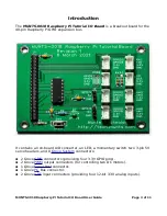
Introduction.............................................................................................................3
Button......................................................................................................................4
LED..........................................................................................................................4
Analog Inputs..........................................................................................................4

Pin Mapping.........................................................................................................4

Pulse Width Modulated DC Motor Driver Outputs....................................................5

Pin Mapping.........................................................................................................5
Alternate PWM Device Tree Overlay Command for Cytron MD13S......................5
Pin Mapping.........................................................................................................5

Servo Headers.........................................................................................................6

Pin Mapping.........................................................................................................6

Serial Port................................................................................................................7

Raspberry Pi 4 Extra Serial Port...........................................................................7

I

2

C Bus Controller.....................................................................................................8

Pin Mapping.........................................................................................................8
Raspberry Pi 4 Extra I

2

C Bus Controller................................................................8

Pin Mapping.........................................................................................................8

Additional Online Documentation............................................................................9
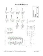
Schematic Diagram...............................................................................................10
Revision History.....................................................................................................11

Board.................................................................................................................11
User Guide.........................................................................................................11

MUNTS-0018 Raspberry Pi Tutorial I/O Board User Guide

Page 2 of 11

Summary of Contents for MUNTS-0018

Page 1: ...UNTS 0018 Raspberry Pi Tutorial I O Board User Guide Revision 2 28 December 2021 by Philip Munts Munts Technologies http tech munts com MUNTS 0018 Raspberry Pi Tutorial I O Board User Guide Page 1 of 11 ...

Page 2: ...nd for Cytron MD13S 5 Pin Mapping 5 Servo Headers 6 Pin Mapping 6 Serial Port 7 Raspberry Pi 4 Extra Serial Port 7 I2 C Bus Controller 8 Pin Mapping 8 Raspberry Pi 4 Extra I2 C Bus Controller 8 Pin Mapping 8 Additional Online Documentation 9 Schematic Diagram 10 Revision History 11 Board 11 User Guide 11 MUNTS 0018 Raspberry Pi Tutorial I O Board User Guide Page 2 of 11 ...

Page 3: ...entary switch two 3 pin 5V servo headers and 8 Grove System connectors 2 Grove GPIO connectors providing four 3 3V GPIO pins 2 Grove PWM output connectors for controlling two DC motors 1 Grove Serial Port connector 1 Grove I2 C Bus connector 2 Grove ADC input connectors providing four 12 bit 3 3V analog inputs MUNTS 0018 Raspberry Pi Tutorial I O Board User Guide Page 3 of 11 ...

Page 4: ...ution of 12 bits values 0 to 4095 inclusive and a full scale range of 0 0 to 3 3V The absolute accuracy of the analog inputs will depend on the accuracy of the Raspberry Pi 3 3V regulator which is connected to the MCP3204 voltage reference input The following device tree overlay command must be appended to boot config txt to enable Linux kernel support for the MCP3204 dtoverlay anyspi spi0 1 dev m...

Page 5: ...ssible to map both PWM outputs to one Grove Connector for motor driver circuits that require clockwise and counterclockwise speed signals instead of speed and direction See the Raspberry Pi device tree overlay documentation for more information about the possible PWM output configurations Alternate PWM Device Tree Overlay Command for Cytron MD13S The Grove Connector on the Cytron MD13S motor drive...

Page 6: ...WM pulse frequency of 50 Hz and a PWM pulse width from 1 0 to 2 0 milliseconds When J2 is used for a servo J6 cannot be used for a motor driver and J2 cannot be used for a servo when J6 is used for a motor driver Likewise when J3 is used for a servo J7 cannot be used for a motor driver and J3 cannot be used for a servo when J7 is used for a motor driver Pin Mapping J2 Pin 1 PWM0 PWM Duty Cycle J3 ...

Page 7: ...ctor J8 Raspberry Pi 4 Extra Serial Port Unlike any of its predecessors the Raspberry Pi 4 has additional hardware serial ports available on the GPIO expansion bus One of these extra hardware serial ports UART3 can be mapped to Grove Connector J5 by appending the following device tree overlay command to boot config txt dtoverlay uart3 This maps Linux serial port device dev ttyAMA1 to Grove Connect...

Page 8: ...s Controller Unlike any of its predecessors the Raspberry Pi 4 has additional I2 C bus controllers available on the GPIO expansion bus One of these extra hardware I2 C bus controllers I2C3 can be mapped to Grove Connector J5 by appending the following device tree overlay command to boot config txt dtoverlay i2c3 This maps Linux I2 C bus controller device dev i2c 3 to Grove Connector J5 You may nee...

Page 9: ...seeedstudio com Grove_System MCP3204 Analog to Digital Converter https www microchip com wwwproducts en MCP3204 Raspberry Pi device tree overlays https github com raspberrypi firmware blob master boot overlays README Raspberry Pi GPIO https www raspberrypi org documentation usage gpio MUNTS 0018 Raspberry Pi Tutorial I O Board User Guide Page 9 of 11 ...

Page 10: ...Schematic Diagram MUNTS 0018 Raspberry Pi Tutorial I O Board User Guide Page 10 of 11 ...

Page 11: ...ry Board Revision 1 6 March 2021 First revision User Guide Revision 1 23 December 2021 First revision Revision 2 Fixed some minor formatting errors MUNTS 0018 Raspberry Pi Tutorial I O Board User Guide Page 11 of 11 ...

Reviews: