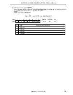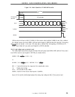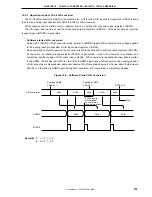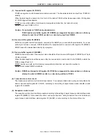
CHAPTER 13 SERIAL INTERFACE 20
User’s Manual U13045EJ2V0UM00
166
(1) Transmit shift register 20 (TXS20)
TXS20 is a register in which transmission data is prepared. The transmission data is output from TXS20 bit-
serially.
When the data length is seven bits, bits 0 to 6 of the data in TXS20 will be transmission data. Writing data
to TXS20 triggers transmission.
TXS20 can be written with an 8-bit memory manipulation instruction, but cannot be read.
RESET input sets TXS20 to FFH.
Caution Do not write to TXS20 during transmission.
TXS20 and receive buffer register 20 (RXB20) are mapped at the same address, so that any
attempt to read from TXS20 results in a value being read from RXB20.
(2) Receive shift register 20 (RXS20)
RXS20 is a register in which serial data, received at the RxD20 pin, is converted to parallel data. Once one
entire byte has been received, RXS20 transfers the reception data to receive buffer register 20 (RXB20).
RXS20 cannot be manipulated directly by a program.
(3) Receive buffer register 20 (RXB20)
RXB20 holds receive data. New receive data is transferred from receive shift register 0 (RXS20) per 1 byte
of data received.
When the data length is specified as seven bits, the receive data is sent to bits 0 to 6 of RXB20, in which the
MSB is always fixed to 0.
RXB20 can be read with an 8-bit memory manipulation instruction, but cannot be written to.
RESET input makes RXB20 undefined.
Caution RXB20 and transmit shift register 20 (TXS20) are mapped at the same address, so that any
attempt to write to RXB20 results in a value being written to TXS20.
(4) Transmission control circuit
The transmission control circuit controls transmission. For example, it adds start, parity, and stop bits to the
data in transmit shift register 20 (TXS20), according to the setting of asynchronous serial interface mode
register 20 (ASIM20).
(5) Reception control circuit
The reception control circuit controls reception according to the setting of asynchronous serial interface mode
register 20 (ASIM20). It also checks for errors, such as parity errors, during reception. If an error is detected,
asynchronous serial interface status register 20 (ASIS20) is set according to the status of the error.
Summary of Contents for mPD789101
Page 2: ...2 User s Manual U13045EJ2V0UM00 MEMO...
Page 10: ...10 User s Manual U13045EJ2V0UM00 MEMO...
Page 16: ...User s Manual U13045EJ2V0UM00 16 MEMO...
Page 46: ...User s Manual U13045EJ2V0UM00 46 MEMO...
Page 72: ...72 User s Manual U13045EJ2V0UM00 MEMO...
Page 86: ...User s Manual U13045EJ2V0UM00 86 MEMO...
Page 94: ...User s Manual U13045EJ2V0UM00 94 MEMO...
Page 102: ...User s Manual U13045EJ2V0UM00 102 MEMO...
Page 128: ...User s Manual U13045EJ2V0UM00 128 MEMO...
Page 148: ...User s Manual U13045EJ2V0UM00 148 MEMO...
Page 162: ...User s Manual U13045EJ2V0UM00 162 MEMO...
Page 218: ...User s Manual U13045EJ2V0UM00 218 MEMO...
Page 238: ...User s Manual U13045EJ2V0UM00 238 MEMO...
Page 240: ...User s Manual U13045EJ2V0UM00 240 MEMO...
Page 256: ...User s Manual U13045EJ2V0UM00 256 MEMO...
Page 258: ...258 User s Manual U13045EJ2V0UM00 MEMO...


