background image


IS-S04G1LC-S User Manual


IS-S04G1LC User Manual C                                    Page 11 of 13 

www.nkkswitches.com 

• 

engineering@nkkswitches.com


1120 

8. ASCII Hex 

 
All USB data is sent as ASCII hex as a safety measure to avoid being interpreted as a command. 
ASCII hex is a normal data byte split into two halves and converted to their ASCII equivalent (see 

www.asciitable.com

). Therefore, all data received will be in the 0x30-0x46 number range, and 

anything received outside that is invalid. For example: 
 
Data to be sent is 0x3D. 
Each nibble is assigned its own byte: 0x3 and 0xD. 
Each of those bytes is converted to ASCII equivalent: 0x33 0x44 (0x33 is the ASCII number ‘3’. 0x44 
is the ASCII letter ‘D’). 
 
Receiving is the same process reversed: 
 
Data received is 0x41 0x37. 
Each byte converted from the ASCII equivalent is 0xA 0x

7 (0x41 is the ASCII letter ‘A’, 0x37 is the 

ASCII number ‘7’). 
Combine the two bytes to get the data byte 0xA7. 


Summary of Contents for IS-S04G1LC-S

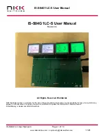
Page 1: ...S04G1LC S User Manual Revision C All Rights Reserved Worldwide NKK Switches makes no warranty for the use of these products and assumes no responsibility for any errors which may appear in this docum...

Page 2: ...om 1120 Table of Contents 1 LCD 64x32 SmartDisplay Switch 3 2 General IS S04G1LC S Features 4 3 Electrical Specifications 5 4 Images and Backlights 6 5 Operational Overview 8 6 Saving Images Using Eng...

Page 3: ...ories down to function specific actions This reduces the need for complicated controls and shortens the time for training by only displaying relevant options and commands Backlight colors can be used...

Page 4: ...switches toggle between ON OFF corresponding control Eight level PWM control for each light or fan Holding any of the switches down for about 2 5 second allow for changing the PWM level Pressing the s...

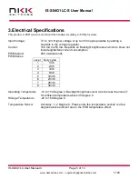
Page 5: ...ent 100 mA to 250 mA Depends on Backlight brightness and colors Does not include lights fans current consumption PWM period 459 microseconds PWM duties Level Duty cycle 1 1 36 2 2 36 3 3 36 4 8 36 5 1...

Page 6: ...communicator images must be saved in the proper format LCD 64x32 Monochrome bitmap bmp 64x24 pixels There are 11 images associated with the light fan control system next page The Backlights can be mod...

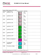
Page 7: ...Light FAN 1 ON FF white 0002 Light FAN 2 ON FF white 0003 Light FAN 3 ON FF white 0004 Light FAN 4 ON FF white 0005 Light FAN 1 OFF 33 Green 0006 Light FAN 2 OFF 33 Green 0007 Light FAN 3 OFF 33 Green...

Page 8: ...at the same time switch 1 display image of address 10 and the backlight brightness level Releasing and pressing the switch 1 will cycle through the 8 brightness levels When the switch is released for...

Page 9: ...drop down menu at the top select the COM port of the system usually the last one 3 Click the Open Port button 4 Press the call button and verify the system responds with 61 in blue text in the left te...

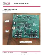
Page 10: ...IS S04G1LC S User Manual IS S04G1LC User Manual C Page 10 of 13 www nkkswitches com engineering nkkswitches com 1120 7 Board Connections Dimension 3 2 x 3 67 Cutout PDF file...

Page 11: ...Therefore all data received will be in the 0x30 0x46 number range and anything received outside that is invalid For example Data to be sent is 0x3D Each nibble is assigned its own byte 0x3 and 0xD Ea...

Page 12: ...bbles ASCII A byte value representing a symbol Communication There are two formats to transmit a byte Format 1 Hex format A hex byte is transmitted without any change to it xxH will be used to denote...

Page 13: ...hes disclaims any liability or warranty obligation with respect to any product that is misused damaged by any user or not used in conformity with all applicable product specifications NKK SWITCHES HER...

Reviews: