Page 40 · SumoBot – Mini Sumo Robotics
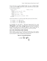
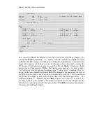
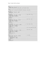
' -----[ Variables ]-------------------------------------------------------
irBits VAR Nib ' storage for IR target data
irLeft VAR irBits.BIT1
irRight VAR irBits.BIT0
' -----[ Program Code ]----------------------------------------------------
Main:
DO
FREQOUT LfIrOut, 1, 38500 ' modulate left IR LED
irLeft = ~LfIrIn ' read input (1 = target)
FREQOUT RtIrOut, 1, 38500 ' modulate right IR LED
irRight = ~RtIrIn ' read input (1 = target)
DEBUG HOME,
"L R", CR,
"----", CR,
BIN1 irLeft, " ", BIN1 irRight
PAUSE 20
LOOP
END
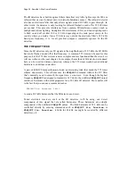
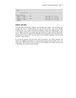
Two bit-sized variables are declared to store the value of each IR detector output. The
command
FREQOUT LfIrOut, 1, 38500
sends the [unfiltered] modulation signal
to the left IR LED, causing it to flash on and off rapidly. The harmonic contained in this
signal either bounces off an object, or not. If it bounces off an object and is seen by the
IR detector, the IR detector sends a low signal to I/O pin
LfIrIn
. Otherwise, the IR
detector sends a high signal to
LfIrIn
. The bitwise invert operator (~) is used so that a
"hit" (reflection from the opponent) is indicated by "1" and a "miss" is indicated by a "0."
So long as the next command after the
FREQOUT
command is the one testing the state of
the IR detector’s output, it can be saved as a variable value in RAM. This is possible as
the IR detector output is held active a short time after the signal goes away. The
statement
irLeft = ~LfIrIn
checks
LfIrIn
, and saves the value (“1” for hit or “0”
for miss) in the
irLeft
bit variable. This process is repeated for the other IR pair, and the
IR detector’s output is saved in the
irRight
variable. The
DEBUG
statement then displays
the values in the Debug Terminal.
Summary of Contents for Boe-Bot
Page 1: ...SumoBot Mini Sumo Robotics Assembly Documentation and Programming VERSION 2 1...
Page 4: ......
Page 9: ...Preface Page ix...
Page 10: ......
Page 20: ......
Page 32: ......
Page 54: ......
Page 74: ......
Page 76: ......
Page 77: ...Appendix D SumoBot PCB Schematic Page 67 Appendix D SumoBot PCB Schematic...


