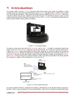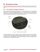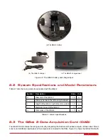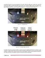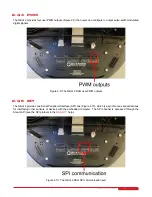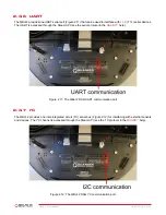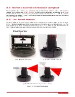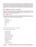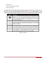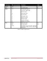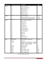
Figure 2.5: The QBot 2 DAQ sensor mounting rows
2.3.1 Digital Input/Output Pins (DIO)
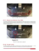
The user DIO channels (Figure 2.6) are set as inputs by default. The DIO channels need to be configured as either
inputs (or outputs, but not both) using the HIL Initialize block. Also, if an output needs to be in a known state on
power up, it is recommended that a 10k resistor is put from the I/O to
5
V
or
GND
as needed. The DIO channels are
accessed through the HIL API.
Figure 2.6: The QBot 2 DAQ user digital I/O
2.3.2 Analog inputs
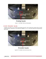
The QBot 2 provides four user analog input channels (Figure 2.7) that are rated for signals between
0
−
5
V
and
uses 12-bit analog to digital converters (ADCs). The analog inputs are accessed through the HIL API.
QBOT 2 - User Manual
8


