

Page 2
32500-90(N)
3.3 JUMPERS
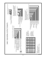
W1 JUMPERS A, B, and C, determine serial output format. Jumper
confi gurations and associated output format are listed below: 1 signi-
fi es that jumper is installed, 0 signifi es that jumper is omitted. See the
SERIAL FORMAT DIAGRAM in the Appendix for more details.
A B C
SERIAL OUTPUT FORMAT
0 0 0
ASCII Ouput
0 0 1
Polled ASCII
0 1 0
NMEA1
0 1 1
NMEA2
1 0 0
RMYT
1 0 1
PRECIP
1 1 0
PRECIP POLLED
1 1 1
SOFTWARE Mode
ASCII and RMYT formats force the serial baud rate to 9600. NMEA
formats force the baud rate to 4800.
ASCII and POLLED ASCII are general purpose outputs that may be
used with the YOUNG 26800 or devices that can communicate seri-
ally. NMEA outputs are generally for marine applications. RMYT is a
proprietary format for use with the YOUNG Wind Tracker.
PRECIP and PRECIP POLLED formats confi gure VIN4 to count tips
from a tipping bucket precipitation gauge. (Requires a 10K ohm resis-
tor between EXC and VIN4.)
SOFTWARE mode allows output format and other parameters to be
set using serial commands. Please see section 4.0 SERIAL COMMU-
NICATION and the SERIAL FORMAT DIAGRAM for more informa-
tion.
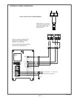
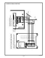
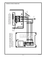
W2 & W3 JUMPERS determine output connection type. Only one
connection type may be used at a time. Please refer to the WIR-
ING DIAGRAM in the Appendix for jumper location and connection
details.
JUMPERS OUTPUT
TYPE
VOUT
Calibrated output for wind speed and direction.
OUT1 0-5000mV = 0-100 m/s Wind Speed
OUT2 0-5000mV = 0-360 degrees Wind Direction
232
RS-232 full duplex serial
485
RS-485 half duplex serial
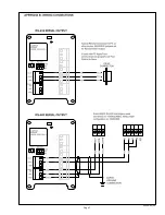
4.0 SERIAL COMMUNICATION
The 32500 uses either full-duplex RS-232 or half-duplex RS-485
signals for serial communication. RS-232 is the most simple and op-
erates up distances of 30m (100ft). The RS-485 option is prefered in
electrically noisy environments, in applications where multiple units
must be networked, or in NMEA marine applications where RS-485
signals are required.
The full duplex RS-232 connection may transmit and receive serial
data at the same time.
The RS-485 connection is half-duplex meaning the unit cannot trans-
mit and receive at the same time. The 32500 internally manages the
switch between modes.
Many applications require the 32500 to transmit only. However,
RS-485 applications that require polling the 32500 or sending com-
mands to it require that the externally connected serial device must
be capable of managing its own half-duplex switching from transmit
to receive.
At low baud rates with proper cable installation and connections,
transmission distances up to 7km (4mi) are possible using RS-485.
Baud rates of 1200, 4800, 9600, 19.2K, and 38.4K baud are avail-
able. Most jumper-selected output formats force the baud rate to a
predetermined value. All serial signals use 1 start, 8 data, and 1 stop
bit. Any externally connected serial device must be set to the same
baud rate as the 32500.
4.1 POLLING
When the serial output format is ASCII POLLED or PRECIP
POLLED, the 32500 sends data only when it receives a serial polling
command:
Ma!
where ‘a’ is the unique address of the unit. The default address is ‘A’
but any alphanumeric character may be used (see POLLING CHAR-
ACTER in section 4.2 SERIAL COMMANDS).
See the SERIAL FORMAT DIAGRAM for details on ASCII POLLED
data format.
4.2 SERIAL COMMANDS
Serial commands configure operating parameters and perform
calibrations.
While most W1 JUMPER settings configure the 32500 to use
predetermined parameters, the SOFTWARE mode allows
operational parameters to be uniquely configured by serial
commands. The parameters are retained even when power is
removed.
Commands may be sent using a PC and simple communica-
tions programs such as HyperTerm or any other properly con-
figured serial device. All commands that begin with CMD must
end with a carriage return (ASCII 13).
Commands may be sent at any time but it may be more conve-
nient to pause 32500 serial output. This is especially necessary
with half-duplex RS-485 communication.
Command Description
CMD100 OPERATE
CMD110 PAUSE
CMD200 n
DAMPING (0=NONE, 1=FAST, 2=SLOW)
CMD210
n FORMAT
0
ASCII
1
ASCII
POLLED
2 NMEA (KNOTS, DIR)
3 NMEA (KNOTS, DIR, TEMP, RH, BARO
4
RMYT
5
PRECIP
6 PRECIP POLLED
7
ASCII
2
9
DIAGNOSTIC
CMD220 n
OUTPUT RATE (0=15Hz, 1=0.1Hz, 2=2Hz)
CMD230 c
POLL CHARACTER (0-9, A-Z)
CMD240 nn BAUD RATE
(12=1200, 48=4800, 96=9600, 192=19200, 384=38400)
CMD250 n
INPUT TYPE (1=PULSE/POT, 2=VIN3/VIN4)
CMD900
REPORT PARAMETER SETTINGS
CMD910
START COMPASS CALIBRATION
CMD920
STOP COMPASS CALIBRATION
X
Alternative command to enter OPERATE mode
3xESC
Alternative command to PAUSE
3xCNTL-S
Alternative command to START compass calibration
3xCNTL-X
Alternative command to STOP compass calibration
DAMPING determines the amount of averaging applied to the
compass measurement.
FORMAT determines serial output format. See Appendix for fur-
ther details. PRECIP formats substitute tipping bucket precipi-
tation counts for the VIN4 voltage measurement. ASCII 2 omits
VIN measurement values from the output string.
Summary of Contents for 32500
Page 5: ...Page 4 32500 90 N...
Page 6: ...Page 5 32500 90 N...
Page 7: ...Page 6 32500 90 N...
Page 8: ...Page 7 32500 90 N...
Page 9: ...Page 8 32500 90 N...
Page 10: ...Page 9 32500 90 N...


