M7 GX Technical Manual
24
Raveon Technologies Corp.
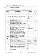
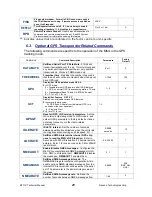
CBIT
CBIT XX
Clears output bits,
XX
is hexadecimal format. Any bit
in x set to 1 will cause the same output bit in the modem’s
output register to be cleared to 0. No bits get set. X=C3 to set
bits 0, 1, 14, 15. To read the output bit register, enter
CBIT
with
no parameter or better to use
GETOUT
command.
0-FF
FAILSAFE
FAILSAFE A B command sets the minimum message interval,
and the default digital output state if an over-the-air MIMIC
message is not received within the failsafe period. A is the
minimum period, and B is the power-on ASCII hex value of the
digital outputs, and also B default values are used if the failsafe
interval passes and no MIMIC messages are receive. The B
values are output again if MIMIC was enabled and no messages
received during the MIMIC interval.
A:Required
Message Interval or
interface to transmit
MIMIC data
(Seconds)
B: Default Ascii hex
value to set outputs
to. 00-FF
Disabled
GOUT
GOUT
Get the output bit register in hexadecimal format.
Example: will return
C3
if bits 0, 1, 14, 15 are set(1) and all
other clear (0).
Returns Hex value,
16 bits max.
GINP
GINP
Get the input bit register in hexadecimal format.
Example: will return
C3
if bits 0, 1, 14, 15 are set(1) and all
other clear (0).
Returns Hex value,
16 bits max.
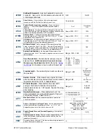
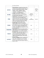
IOPIN
IOPIN XX M
Set the GPIO IO pins on the Tech Series GPIO
front panel to inputs or outputs.
XX
parameter is the
hexadecimal representation of the pins being configured. M is
the mode for the XX pins. Mode M values:
A
:Digital TTL Input,
B
:Digital TTL Output.
C
:Open Drain MOSFET output,
D
:DC
Power switch output.
XX=Hex 00-FF
M=(A,B,C,D)
03 A
04 C
MIMIC
MIMIC mode
. MIMIC X Y
X
number of seconds to TX if input
is low.
Y
is number of seconds between transmissions when
the input is high.
X: 0-255 Y:0-255
0 disabled
SBIT
SBIT XX
Sets output bits,
XX
is hexadecimal format. Any bit in
x set to 1 will cause the same output bit in the modem’s output
register to be set. No bits get cleared. X=C3 to set bits 0, 1, 14,
15. To read the output bit register, enter SETBIT with no
parameter or better to use
GETOUT
command.
SBIT 03
will set
IO1 and IO2. It will not affect IO3 because 03 is 000011 in
binary.
0-FF
TBIT
TBIT XX MMM
Time Bit sets output bits for a specific time,
XX
is hexadecimal format. Any bit in x set to 1 will cause the same
output bit in the modem’s output register to be set.
MMM
is in
mS. 1000=one second, 60000=one minute,…To set bit #3 to 1
for 250mS:
TBIT 4 250
After the time expires, the bits that
was st in XX is cleared to 0.
0-FF
2 – 4000000000
(2mS
–
1100hours)
See Raveon
’
s
Application Note AN161
for details on how the MIMIC mode as SCADA
features work with the M6 radio modem, and now better the MIMIC and SDACA features
can do when the M6 is within the Tech Series enclosure with the GPIO interface.
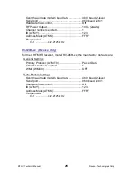
6.4. Factory Default Settings
RV-M6-xx (Transceiver)
For the UHF M6, model RV-M6-UC, the main factory defaults are:
General Settings
Primary Protocol: (ATMT 0) ............................... Packet Data
WMX (WMX 0) .................................................. OFF
Data Modem Settings:


