43
Raveon Technologies Corp.
8.4.
Digital Inputs (Trigger Bits)
The stock
GX
Transponder has 3 digital inputs. The status of these input bits is
transmitted every time the M6 reports its position.
When configuring an M6 GPS transponder, you may configure any or all of the
digital inputs t
o be “
Trigger Bits
”. The status of all bits is transmitted every time,
but when a bit is designated as a
Trigger Bit
, it will also cause the M6 to wake-up
if it is sleeping, and triggers it to send a transmission as soon as it can. They are
called Trigger Bits because the bits can be used to trigger the M6 to transmit at
the faster TXRATE instead of the slower IDLERATE.
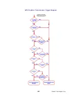
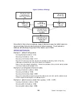
The M6 has low-power modes and an idle transmission rate (IDLERATE). The
M6 may be configured to use bits designated as
Trigger Bits
to come out of low-
power mode or transmit at a faster rate. But, regardless of the rate or Trigger Bit
designation, the status of the digital input bits will be transmitted along with each
position report. If a bit is designated as a Trigger Bit, its state will be latched
when it triggers, and the latched state is transmitted. Older version of firmware
do not latch the state, and thus the My reports the state of the bit at the moment
the position is transmitted. C2 and higher report the latched state of the trigger
bit.
Bits that are designated
Trigger Bits
are digital inputs that trigger the
RV-M6
to
trigger a report of the M6’s position and status. Normally these inputs are used
for RS-232 signals, but they may be used for general-purpose digital inputs. The
RV-M6
may be configured to trigger a position/status report based upon the
digital input bits state.
Important: If the digital input function is not needed, the
TRIGBITS
setting must
be set to
0
. This is the factory-default setting, and unexpected transmission may
happen if the digital inputs are enabled and not used.
If you are not using digital inputs,
TRIGBITS
must be set to 0. (
TRIGBITS 0
command)
If the
RV-M6 GX
was configured to transmit less-often when it is not moving
(
IDLERATE
command), activation of the digital inputs will override this causing
the unit to report at the interval programmed with the
TXRATE
command.
The digital inputs may be configured to trigger active high, active low, or active
on a change in state. The following table lists the available digital inputs on the
standard RV-M6 GX:
RS-232 Pin
Function
4 - DTR
Input 0
7 - RTS
Input 1
3 - TXD
Input 2
5 - Ground
GND
There are 3 commands that must be configured to use the digital inputs:

