background image

Controller functions

Page 24

UPT-606

9.4.1

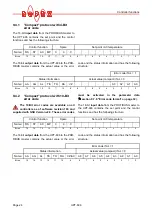
"Compact" protocol with 4-Bit 
error code

The 16-bit 

input data

 from the PROFIBUS master to

the UPT-606 contains the set point and the control
functions and has the following structure:

The 16-bit 

output data

 from the UPT-606 to the PRO-

FIBUS master contains the actual value or the error

code and the status information and has the following
structure:

9.4.2

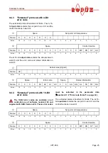
"Compact" protocol with 10-Bit 
error code

The 10-Bit error codes are available on all
controllers as of software revision 100 and

supplied with GSD Version v2.0. These error codes

must be activated in the parameter data
(

section 9.7.9 "Error code format" on page 32).

The 16-bit 

input data

 from the PROFIBUS master to

the UPT-606 contains the set point and the control
functions and has the following structure:

The 16-bit 

output data

 from the UPT-606 to the PRO-

FIBUS master contains the actual value or the error

code and the status information and has the following
structure:

Control function

Spare

Set point / AC temperature

Name:

RS

ST

AC

MP

0

0

0

Bit  no.:

15

14

13

12

11

10

9

8

7

6

5

4

3

2

1

0

Error code if AL = 1

Status information

Actual value (compact) if AL = 0

Name:

AA

AG

AL

TE

TO

RA

VZ

A3

A2

A1

A0

Bit  no.:

15

14

13

12

11

10

9

8

7

6

5

4

3

2

1

0

!

Control function

Spare

Set point / AC temperature

Name:

RS

ST

AC

MP

0

0

0

Bit  no.:

15

14

13

12

11

10

9

8

7

6

5

4

3

2

1

0

Error code if AL = 1

Status information

Actual value (compact) if AL = 0

Name:

AA

AG

AL

TE

TO

RA

VZ/A9

A8

A7

A6

A5

A4

A3

A2

A1

A0

Bit  no.:

15

14

13

12

11

10

9

8

7

6

5

4

3

2

1

0

Summary of Contents for CIRUS UPT-606

Page 1: ...agement functions i e controlling the temperature of the heating element Important features Microprocessor technology Complete control via PROFIBUS DP interface Automatic zero calibration AUTOCAL Automatic configuration of the secondary voltage and current ranges AUTORANGE as of Software revision 100 Automatic frequency adjustment Large current and voltage range Booster connection as standard 0 10...

Page 2: ...standard 14 7 7 Wiring diagram with booster connection 15 8 Startup and operation 16 8 1 View of the controller 16 8 2 Controller configuration 16 8 3 Heating element 18 8 4 Startup procedure 19 9 Controller functions 21 9 1 Indicators and controls 21 9 2 PROFIBUS communication up to SW Rev 015 as of SW Rev 100 23 9 3 Device master file GSD 23 9 4 PROFIBUS protocol 23 9 5 Input data 26 9 6 Output ...

Page 3: ...repair 1 3 Impulse transformer A suitable impulse transformer is necessary to ensure that the control loop functions perfectly This transformer must be designed according to VDE 0570 EN 61558 isolating transformer with reinforced insulation and have a one section bobbin When the impulse transformer is installed suitable shock protection must be provided in accordance with the national installation...

Page 4: ...ctrical overloading natural wear incorrect or negligent handling chemical influences or mechanical overloading as well as devices that have been modified relabeled or otherwise altered by the customer for example in an attempt to repair them or install additional components are excluded from the warranty Warranty claims must be examined in the factory and approved by ROPEX 2 Application This CIRUS...

Page 5: ...EX GmbH in an intensive development process Users who follow our technical recommendations will profit from the unique functionality of this technology which reduces the customer s effort for installation commis sioning and maintenance to a minimum 3 1 Temperature controller The controller calculates the resistance of the heating element by measuring the current and voltage at a high sampling rate...

Page 6: ...e con troller UPT 606 and the plug in connections make this controller easy to install 3 2 Current transformer The PEX W2 or PEX W3 current transformer supplied with the CIRUS UPT 606 controller is an integral part of the control system Only this original ROPEX current transformer is allowed to be used Never attempt to operate the current transformer with open connections 3 3 Booster If the maximu...

Page 7: ...S temperature controller Impulse transformer ITR x Designed according to VDE 0570 EN 61558 with a one section bobbin Optimized for impulse operation with CIRUS temperature controllers Specified according to the heatsealing application ROPEX Application Report Communication interface CI USB 1 Interface for connecting a RESISTRON temperature controller with diagnostic inter face DIAG to the PC USB p...

Page 8: ... type and temperature range As of software revision 100 The temperature range and temperature coefficient settings can also be specified by means of the ROPEX visualization software section 9 11 Diagnostic inter face visualization software as of software revision 100 on page 39 in addition to the rotary coding switch see below Temperature range 200 C 300 C 400 C or 500 C Temperature coefficient 40...

Page 9: ...nting on a horizontal top hat rail End holders to mechanical fix the controller must be fitted at both ends for moun ting on a vertical top hat rail Weight Approx 0 7kg incl connector plug in parts Housing material Plastic polycarbonate UL 94 V0 Connecting cables Type cross sections Rigid or flexible 0 2 2 5mm AWG 24 12 Plug in connectors If ferrules are used they must be crimped in accordance wit...

Page 10: ...nd lay it twisted to the con troller UML 1 voltage measurement cable section 4 Accessories and modifications on page 6 5 Ensure an adequate cable cross section for the pri mary and secondary circuits Application Report 6 Use only ROPEX impulse transformers or transfor mers approved by ROPEX Please note the power the duty cycle and the primary and secondary voltages Application Report 7 2 Installat...

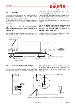
Page 11: ...iagram standard on page 14 and the ROPEX Application Report The information provided in section 7 1 Installation steps on page 10 must also be heeded additionally 5 Connect the CIRUS temperature controller to the PROFIBUS master using a cable according to IEC 61158 Check the tightness of all the system connec tions including the terminals for the impulse transformer windings 6 Make sure that the w...

Page 12: ... Series Relay Kb Load break all pole e g in combination with the alarm output of the temp controller ROPEX recommendation When using a series resistor RV 1 the relay Kb shall be installed Impulse Transformer Designed according to VDE 0570 EN 61558 isolating transformer with reinforced insulation Connect core to ground Use transformers with a one section bobbin The power duty cycle and voltage valu...

Page 13: ... application For more technical information Line filter docu mentation It is permissible to supply several CIRUS control loops with a single line filter provi ding the total current does not exceed the maximum current of the filter The wiring instructions contained in section 7 3 Power supply on page 12 must be observed 7 5 Current transformer PEX W3 The PEX W3 current transformer supplied with th...

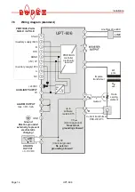
Page 14: ... GND 5 24V IN 5V OUT PROFIBUS controller electrically isolated 11 9 10 8 4 3 2 1 15 16 18 17 C ATR _ ANALOG OUTPUT 0 10VDC Ground Must be grounded externally to prevent electrostatic charging R IR UR Current transformer PEX W2 W3 twisted Impulse transformer Heat sealing element LINE Line filter LF xx480 sec U2 prim U1 0V Internnal ground No external grounding allowed 0V Internnal ground No externa...

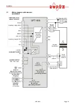
Page 15: ...24V IN 5V OUT PROFIBUS controller electrically isolated 11 9 10 8 4 3 2 1 15 16 18 17 C ATR _ ANALOG OUTPUT 0 10VDC Ground Must be grounded externally to prevent electrostatic charging 0V Internnal ground No external grounding allowed R Current transformer PEX W2 W3 twisted Impulse transformer IR UR Heat sealing element LINE Booster NC NC 2 4 IN OUT 1 3 Line filter LF xx480 sec U2 prim U1 0V Inter...

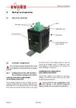
Page 16: ...tage is configured in the range from 0 4VAC to 120VAC and the current in the range from 30A to 500A If the voltage and or the current is outside the permissible range a detailed error mes sage appears on the controller see section 9 13 Error messages on page 40 Configuration with coding switches up to software revision 015 Set the DIP switches for matching the secondary voltage U2 and the secondar...

Page 17: ...7 Parameter data on page 30 If the switch is set to 9 as of software revision 100 more temperature ranges and alloys can be selected by means of the ROPEX visualization software see section 9 11 Diagnostic interface visualization soft ware as of software revision 100 on page 39 3 2 1 4 5 ON OFF 1 10V 6 60V 20 120V ON OFF OFF OFF ON OFF OFF OFF ON 30 100A 60 200A 120 400A OFF ON ON OFF OFF ON DIP s...

Page 18: ...ROPEX visu alization software see section 9 11 Diagnostic interface visualization software as of software revision 100 on page 39 8 3 Heating element 8 3 1 General The heating element is a key component in the control loop since it is both a heating element and a sensor The geometry of the heating element is too complex to be discussed at length here We shall therefore only refer to a few of the m...

Page 19: ...pply voltage specified on the nameplate of the controller must be identical to the line voltage that is present in the plant or machine The line fre quency is automatically detected by the tempera ture controller in the range from 47 63Hz 3 In case of controllers up to software revision 015 the settings of the DIP switches on the controller are indicated in the ROPEX Application Report and depend ...

Page 20: ...eans of the PROFIBUS protocol set point and set the ST bit The RA bit controller active is then acti vated and the HEAT LED lights up The heating and control process can be observed at the actual value output The controller is functioning correctly if the tempera ture which corresponds to the signal change at the analog output or the actual value in the PROFIBUS protocol has a harmonious motion in...

Page 21: ...RM red LED HEAT yellow LED OUTPUT green LED AUTOCAL yellow LED 24V SUPPLY green LED BUS PWR OK green LED µC PWR OK green LED DATA EXC green LED Lights up or blinks to indicate an alarm Lit during heating phase Indicates pulses in measurement mode In control mode luminous intensity is proportional to heating current Remains lit for duration of AUTOCAL process Lit if external 24VDC power supply is p...

Page 22: ...rent Green LED remains lit as long as PROFIBUS data is beeing exchanged with master Red LED lights up or blinks to indicate alarm 4 3 2 1 9 8 6 5 10 11 7 12 13 14 15 16 17 18 ROPEX INDUSTRIE ELEKTRONIK RESISTRON μP Controller AUTOCAL OUTPUT HEAT ALARM POWER ON DATA EXCHANGE Profibus Yellow LED lit during heating phase LED Blinks slowly 1Hz Blinks fast 4Hz Lit continuously AUTOCAL yellow No PROFIBU...

Page 23: ...ision 015 i e a bus fault in the PROFIBUS master 9 3 Device master file GSD Configuring tools for the PROFIBUS DP master that must be configured interpret the contents of the slave device master files and use them to create a master parameter set for the PROFIBUS master which is responsible for useful data communication The ROxy07EA GSD file xy GSD Version e g 15 for ver sion v1 5 of the UPT 606 c...

Page 24: ...The 16 bit input data from the PROFIBUS master to the UPT 606 contains the set point and the control functions and has the following structure The 16 bit output data from the UPT 606 to the PRO FIBUS master contains the actual value or the error code and the status information and has the following structure Control function Spare Set point AC temperature Name RS ST AC MP 0 0 0 Bit no 15 14 13 12 ...

Page 25: ...code format on page 32 The extended protocol transfers 2x16bits The 2x16 bit input data contains the set point in word and the control functions in word Spare Set point AC temperature Name 0 0 0 0 0 0 0 Bit no 15 14 13 12 11 10 9 8 7 6 5 4 3 2 1 0 Spare Control function Name 0 0 0 0 0 0 0 0 0 0 0 0 MP RS ST AC Bit no 15 14 13 12 11 10 9 8 7 6 5 4 3 2 1 0 Actual value signed Name VZ Bit no 15 14 13...

Page 26: ...r than 40 C or if the selected value varies an error message appears error codes 115 and 116 section 9 13 Error messages on page 40 The AUTOCAL request AC bit 1 is executed by the controller providing the AUTOCAL function is not disabled The automatic calibration process takes about 10 15 seconds The heatsealing element is not heated during this process The yellow LED on the front panel lights up ...

Page 27: ...n only fault nos 5 and 7 As of software revision 100 201 203 901 913 are evaluated and output by the fault diagnosis function The power section is not acti vated in this state and no measuring impulses are generated Consequently the actual value is no longer updated The reset request is not processed until the RS bit is reset The PROFIBUS communication is not interrupted by a controller reset The ...

Page 28: ...s set if the actual temperature exceeds 95 of the set temperature As soon as the control mode is exited ST bit 0 or an alarm is signaled AL bit 1 this status bit is reset again 9 6 5 Temperature OK TO The UPT 606 checks whether the actual temperature is within a settable tolerance band OK window on either side of the set temperature The lower and upper limits of the tolerance band can be changed i...

Page 29: ...two or three digit error codes are output If two digit error codes are specified some faults are grouped together three digit error codes enable a fault to be identified more preci sely In the compact protocol the error code appears instead of the actual value in bits 0 3 error code format 4 bit or 0 9 error code format 10 bit In the extended protocol the error code appears in the second word at b...

Page 30: ... C 8 Heating time limit 100ms units 0 0 99 0 9 9s 9 Extended controller dignostis acti vated deactivated activated 10 Measuring impulse duration 17 17 30 1 7 3 0ms 11 Data format High Low byte Intel High Low byte Intel Low High byte Moto rola 12 Correction factor Co 100 25 200 13 14 Maximum start temperature 100 C 20 500 C 15 Error code format 4 bit 4 bit 10 bit 16 17 Temperature cefficient 1700 p...

Page 31: ...ion It is therefore not possible to adapt the calibration temperature to the pre vailing ambient conditions in the machine As of software revision 100 and supplied with GSD Version v2 0 the calibration temperature can be acti vated for setting by means of the input data by selecting the value 1 in the parameter data The calibration temperature can then be specified via the Set point AC temperature...

Page 32: ... set a measuring impulse that is longer than the default 1 7ms for certain applications 9 7 8 Data format This parameter specifies the order of the bytes Intel high low byte Motorola low high byte in the cyclic data for both input and output data section 9 4 PROFIBUS protocol on page 23 We recommend setting low high byte Motorola for Siemens control lers 9 7 9 Error code format This parameter spec...

Page 33: ...1 protocol extension Setting We advise you not to set this parameter until you have determined the optimum heatsealing parameters tem perature and cooling time for productive operation The starting temperature should be set to approxi mately 50 of the heatsealing temperature for the trial run to enable the optimum working parameters to be established correctly 9 7 12 Temperature diagnosis as of GS...

Page 34: ...ime is longer than the parameterized time the corresponding error code 304 is indicated and the alarm relay is switched section 9 13 Error mes sages on page 40 The Heatup timeout function must be acti vated by means of the PROFIBUS parameter data section 9 7 Parameter data on page 30 or the DPV1 protocol extension section 9 8 DPV1 protocol extension as of GSD Version v2 0 on page 35 default settin...

Page 35: ...section 9 8 DPV1 pro tocol extension as of GSD Version v2 0 on page 35 Default setting Hold mode off 9 8 DPV1 protocol extension as of GSD Version v2 0 Text in preparation 9 8 1 Identification and maintenance I M functions Text in preparation 9 8 2 DPV1 alarm model Text in preparation ACTUAL temp 1 T t t 0 0 Hold off T t 0 ACTUAL indication Hold on T t 0 Hold 2 s T t 0 Hold Hold Hold Hold End of h...

Page 36: ...transfer all parameters that deviate from the static configuration again after restarting the controller or the bus Please contact the manufacturer for more information about how your PLC system sup ports the DPV1 protocol extension DPV1 parameter table of the UPT 606 Default values are printed bold cursive Slot Index Parameter Value range x 255 I M functions IM0 Article number serial number versi...

Page 37: ...1 19 Maximum temperature C 200 500 300 1 21 Temperature diagnosis 0 deactivated 1 activated 1 22 Temperature diagnosis delay time 0 01s steps 0 999 0 1 24 Heatup timeout 0 01s steps 0 999 0 1 26 TO bit Temperature OK 0 off 1 active if Tact Tset 2 active if Tact Tset with latch 1 27 Hold mode 0 off 1 on 2 2s Slot Index Parameter Value range ...

Page 38: ...ne disturbances to be observed extremely effectively and interpreted accordingly The same applies if mutual interference occurs between several neighboring control loops This output is not potential free and might have the potential of the secondary voltage of the impulse transformer External grounding is not allowed If this warning is ignored the con troller will be damaged by frame currents Cont...

Page 39: ...terminals 12 13 14 This relay is set in the factory as follows DE ENERGIZED in operating states A 1 and A 2 but energized if the ST bit is activated in one of these states ENERGIZED in operating state A 3 If the alarm relay is configured opposite to the factory setting section 8 2 4 Configuration of the alarm relay on page 18 these states are reversed C Error code indication via the PROFIBUS proto...

Page 40: ...n two separate tables for controllers up to software revision 015 and as of soft ware revision 100 The block diagram in section 9 14 Fault areas and causes on page 45 permits each fault to be cleared quickly and efficiently 13 voltage levels for fault diagnostics appear at the actual value output of all controllers as of software revision 100 The error messages are differentiated even more finely ...

Page 41: ...se I R signal missing U R signal missing U R and I R signals missing Temperature step down Temperature step up Temperature too low high section 9 7 12 Frequency fluctuation inadmissible line frequency Heatup time too long section 9 7 13 Starting temperature too high section 9 7 11 no line voltage Sync Sig Triac defective Int faut contr defective Int faut contr defective Int faut contr defective Pl...

Page 42: ... of transformer Fault area Run AUTOCAL and or fault area loose contact Run AUTOCAL Cause I R signals incorrect incorrect specification of impulse transformer U R signals incorrect incorrect specification of impulse transformer U R and or I R signals incorrect incorrect specification of impulse transformer Temperature too low AUTOCAL wasn t per formed loose contact ambient temp fluctuates temperatu...

Page 43: ...ation Fault area check configuration Fault area check configuration Cause I R signal incorrect calibration not possible U R signal incorrect calibration not possible U R and I R signals incorrect calibration not possible Temperature fluctuates calibration not possible Ext calibration temperature too high calibration not possible Ext calibration temperature fluctuates calibration not possible STATU...

Page 44: ...ture step Frequency fluctuation inadmissible line frequency Internal fault Internal fault controller defective U R and or I R signal incorrect Data error I R signal incorrect calibration not possible U R signal incorrect calibration not possible U R and I R signals incorrect calibration not possible STATUS of alarm relay factory set Energized De Energized gets energized with START signal voltage v...

Page 45: ...mpulse transformer interrupted Secondary circuit interrupted before UR pickoff point Wire break Secondary winding of impulse transformer interrupted UR signal missing Measuring wires interrupted Partial short circuit delta R heating element partially bypassed by conducting part clamp opposite heating bar etc Parallel circuit interrupted Wire break heating element break Contacting to heating elemen...

Page 46: ...ug in jumper for alarm output not connected or incor rectly connected Fault area Explanation Possible causes DIP switches for secondary voltage U2 and current I2 Up to software revision 015 U2 6 60VAC I2 30 100A DIP switches 2 ON 1 3 4 5 OFF These switches are automatically set by the AUTORANGE function on all control lers as of software revision 100 Rotary coding switch for sealing element alloy ...

Page 47: ...ion and or tightening of the terminals including the terminals for the winding connections on the impulse transformer is recommended Dust depo sits on the controller can be removed with dry com pressed air Rotary coding swit ches for station address Station address 01dec Temperature diagnosis X Temperature diagnosis deactivated Heatup timeout X Heatup timeout deactivated 0 0 5 5 1 1 2 2 3 3 4 4 6 ...

Page 48: ...s e g UPT 606 400VAC MOD 01 controller for 400VAC power supply with amplifier for low voltage Art No 660603 800001 must be ordered Current transformer PEX W3 Art No 885105 Line filter LF 480 06 Continuous current 6A 480VAC Art No 885500 35 Continuous current 35A 480VAC Art No 885506 Impulse transformer See ROPEX Application Report for design and ordering information Communiction interface CI USB 1...

Page 49: ...ature meter 7 Dimensions 10 DIP switches 16 DPV1 protocol extension 35 E Error code format 32 Error messages 40 Extended controller diagnosis 32 External switching amplifier 7 15 F Factory settings 46 Fault areas 45 Fault diagnosis 6 Fuse 12 G GSD 23 H Heating element 3 18 Heatsealing element type 8 Heatup timeout 34 I Impulse transformer 3 7 12 48 Input data 26 Installation 9 10 Installation proc...

Page 50: ...ure 33 Startup 16 System diagnostics 39 System monitoring 39 T TCR 18 TE bit 28 Temperature coefficient 18 Temperature diagnosis 33 Temperature indication 38 Temperature meter 6 38 48 Temperature OK 28 Temperature range 8 17 Temperature reached 28 TO bit 28 Transformer 3 7 12 48 Type of construction 8 V View of the controller 16 Visualization software 39 W Wiring 11 12 Wiring diagram 14 15 ...

Reviews: