Acuity AP820 Laser Scanners
Rev. 3.3
39
Private Function
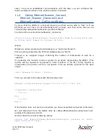
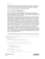
EthernetScanner_WriteData(
ByVal
pScanner
As
IntPtr,
ByVal
Buffer
As Byte
(),
ByVal
Buffersize
As UInteger
)
As Uinteger
Where:
pScanner is the pointer returned by EthernetScanner_Connect
Buffer contains the array of bytes to be sent to the laser
Buffersize is the number of bytes to be sent (i.e. the size of Buffer)
This function returns the number of bytes written on success, and –1 on failure.
The byte array contains two types of bytes; Register Address bytes and Register Data
Values. The order of the bytes in the array must be Register Address first, followed by
any data value bytes which may be required for the particular register.
A byte indicating which Register Address is to be written to must have a 0 in bit 7, and
the Register Address in bits 6 to 0.
A byte indicating what data value to write to the specific register must have a 1 in bit 7,
and the data value in bits 6 to 0.
11.8.1
Examples: Laser on, Triggering
In the following section, we demonstrate how to execute two laser commands (turning
the laser on, and changing the triggering method), as well as how to change a setting
(the Z measurement range). Once these three examples are understood, coding of
any other register related operation should be straight forward by analogy.
For example, let’s consider commands to turn on and to turn off the laser
programmatically. We see in the Register of Functions that the laser on/off function is
at Register Address 12, and that a data value of 0 in bit 0 of the register turns the
laser off, and a data value of 1 in bit 0 turns the laser on.
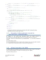
We need a 2-byte array perform these tasks, the first byte will be the Register
Address and the second byte will be the Data Value for the Register (i.e. 0 for off or 1
for on). So we might write the following code to turn the laser off:
Private Function
TurnOffLaser()
As UInteger
Dim
Buffer(1)
As Byte
'Note, VB always adds 1 to the size
Dim
BytesWritten
As UInteger
‘ The first byte will set the Register Address to 12
Buffer(0) = &H0C
'bit 7 is 0, bits 6 to 0 will add to 12.
‘ The second byte will set the data value for the register to 0
Buffer(1) = &H80
'bit 7 is 1, bit 0 is 0
return
EthernetScanner_WriteData(pScanner, Buffer, 2)
End Function
Likewise, to turn the laser back on we would set that register to 1 by putting &H81 in
Buffer(1).
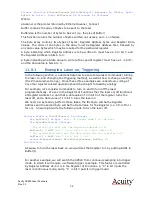
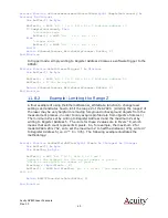
For another example, we will switch the AP820 from continuous sampling into trigger
mode, in which it will require a software trigger to sample. This feature is controlled
by Register Address 20, bit 3, in the Register of Functions. A “0” in bit 3 puts the
laser in continuous mode, and a “1” in bit 3 puts it in trigger mode:

