background image

Presetting an Output Port  

Each  port  has  an  output  register  associated  with  it.  This  register  may  be  written  and  retains  its  value 
whether the port is configured as an input or an output. To preset the value of an output port the program 
should write to the port when it is configured as an input then configure it as an output. 

Writing the Outputs 

The outputs are active true. Writing a one (1) corresponds to 5V while writing a zero (0) corresponds to 0V, 
at the output. 

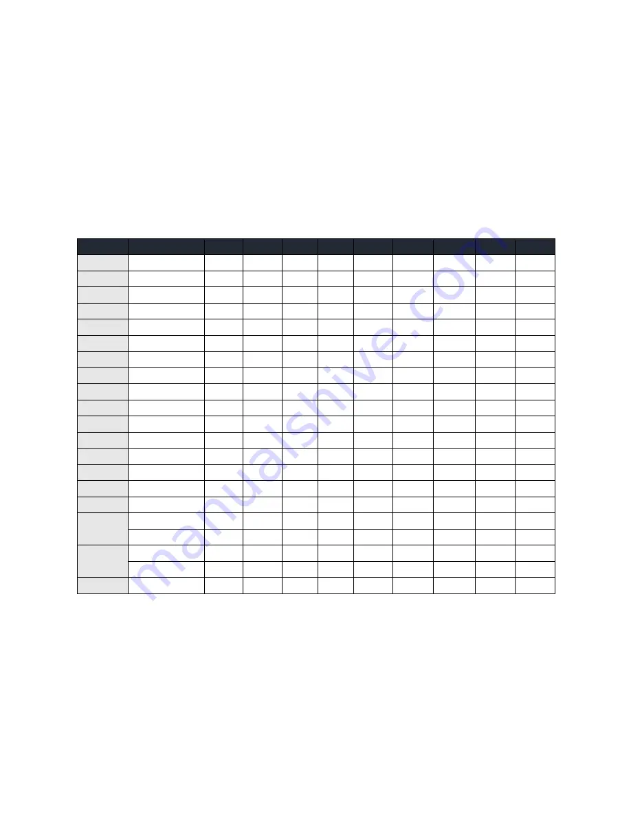
Register Description 

Address


Mode


D7


D6


D5


D4


D3


D2


D1


D0


Base+0


Port A1 

RD/WR  PA1D7  PA1D6  PA1D5  PA1D4  PA1D3  PA1D2  PA1D1  PA1D0 

Base+1


Port B1 

RD/WR  PB1D7  PB1D6  PB1D5  PB1D4  PB1D3  PB1D2  PB1D1  PB1D0 

Base+2


Port C1 

RD/WR  PC1D7  PC1D6  PC1D5  PC1D4  PC1D3  PC1D2  PC1D1  PC1D0 

Base+3


CW Port 1 

WR 

CW1D7 

CW1D4  CW1D3  CW1D2  CW1D1  CW1D0 

Base+4


Interrupt Port 1  RD/WR 

IRQEN1  IRQC11  IRQC10 

Base+5


IntStat Port 1 - 4 

RD 

IRQST4  IRQST3  IRQST2  IRQST1 

Base+8


Port A2 

RD/WR  PA2D7  PA2D6  PA2D5  PA2D4  PA2D3  PA2D2  PA2D1  PA2D0 

Base+9


Port B2 

RD/WR  PB2D7  PB2D6  PB2D5  PB2D4  PB2D3  PB2D2  PB2D1  PB2D0 

Base+A


Port C2 

RD/WR  PC2D7  PC2D6  PC2D5  PC2D4  PC2D3  PC2D2  PC2D1  PC2D0 

Base+B


CW Port 2 

WR 

CW2D7 

CW2D4  CW2D3  CW2D2  CW2D1  CW2D0 

Base+C


Interrupt Port 2  RD/WR 

IRQEN2  IRQC21  IRQC20 

Base+10


Port A3 

RD/WR  PA3D7  PA3D6  PA3D5  PA3D4  PA3D3  PA3D2  PA3D1  PA3D0 

Base+11


Port B3 

RD/WR  PB3D7  PB3D6  PB3D5  PB3D4  PB3D3  PB3D2  PB3D1  PB3D0 

Base+12


Port C3 

RD/WR  PC3D7  PC3D6  PC3D5  PC3D4  PC3D3  PC3D2  PC3D1  PC3D0 

Base+13


CW Port 3 

WR 

CW3D7 

CW3D4  CW3D3  CW3D2  CW3D1  CW3D0 

Base+14


Interrupt Port 3  RD/WR 

IRQEN3  IRQC31  IRQC30 

Base+18


Port A4 

RD/WR  PA4D7  PA4D6  PA4D5  PA4D4  PA4D3  PA4D2  PA4D1  PA4D0 

Base+19


Port B4 

RD/WR  PB4D7  PB4D6  PB4D5  PB4D4  PB4D3  PB4D2  PB4D1  PB4D0 

Base+1A


Port C4 

RD/WR  PC4D7  PC4D6  PC4D5  PC4D4  PC4D3  PC4D2  PC4D1  PC4D0 

Base+1B


CW Port 4 

WR 

CW4D7 

CW4D4  CW4D3  CW4D2  CW4D1  CW4D0 

Base+1C


Interrupt Port 4  RD/WR 

IRQEN4  IRQC41  IRQC40 

IntStat = Interrupt Status 


Summary of Contents for REL-32.PCI

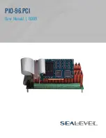
Page 1: ...PIO 96 PCI User Manual 8009...

Page 2: ...CAL INSTALLATION 10 DIGITAL I O INTERFACE 11 PROGRAMMING THE PIO 96 PCI 12 ELECTRICAL CHARACTERISTICS 16 SPECIFICATIONS 17 EXAMPLE CIRCUITS 18 APPENDIX A TROUBLESHOOTING 19 APPENDIX B HOW TO GET ASSIS...

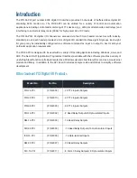
Page 3: ...PIO 96 PCI is designed to be used with a variety of Operating Systems including Windows Linux and DOS The SeaI O API Application Programmer Interface available with the software provides a variety of...

Page 4: ...el of importance used to stress a condition where damage could result to the product or the user could suffer serious injury Important The middle level of importance used to highlight information that...

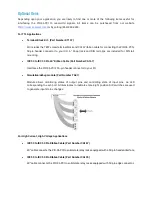
Page 5: ...50 to IDC 50 Pin 40 Ribbon Cable Part Number CA167 Interfaces the PIO 96 PCI s 50 pin header connector to your I O Simulation debug module Part Number TA01 Module allows monitoring status of output p...

Page 6: ...Provides 4 channels of discrete I O interface to monitor AC inputs up to 140V 10mA DC Input Part Number IB5Q Provides 4 channels of discrete I O interface to monitor DC inputs from 3 3V to 32V AC Outp...

Page 7: ...eens that follow 4 A screen may appear with the declaration The publisher cannot be determined due to the problems below Authenticode signature not found Please select the Yes button and proceed with...

Page 8: ...e for as many SeaIO cards as you wish to install Linux Installation You MUST have root privileges to install the software and drivers The syntax is case sensitive Users can obtain a README file includ...

Page 9: ...your editor 12 With the system off and unplugged install your SeaIO PCI card 13 Plug system back in and boot Linux Login as root 14 Load the SeaIO driver by typing seaioload 15 The driver has enabled...

Page 10: ...ly insert the PCI adapter into the slot Make sure that the adapter is seated properly 5 After the adapter has been installed the cables should be routed thru the opening in the bracket This bracket al...

Page 11: ...onfigured via software command as input or output 50 pin Header Connector You will need to install the bracket assembly and cables to the PIO 96 PCI prior to installing it in the PC The PIO 96 PCI s b...

Page 12: ...and utilities both executable and source code are included with SeaI O Further documentation on these samples can be found by selecting Start Programs SeaIO Sample Application Description Information...

Page 13: ...rt 1 4 RD 0 0 0 0 IRQST4 IRQST3 IRQST2 IRQST1 Base 8 Port A2 RD WR PA2D7 PA2D6 PA2D5 PA2D4 PA2D3 PA2D2 PA2D1 PA2D0 Base 9 Port B2 RD WR PB2D7 PB2D6 PB2D5 PB2D4 PB2D3 PB2D2 PB2D1 PB2D0 Base A Port C2 R...

Page 14: ...1 X X 0 1 X 1 1 8B Out In In 1 X X 1 0 X 0 0 90 In Out Out 1 X X 1 0 X 0 1 91 In Out In 1 X X 1 0 X 1 0 92 In In Out 1 X X 1 0 X 1 1 93 In In In 1 X X 1 1 X 0 0 98 In Out In 1 X X 1 1 X 0 1 99 In Out...

Page 15: ...clears any interrupt pending IRQST1 D0 Interrupt status 1 interrupt pending 0 none IRQST2 D1 Interrupt status 1 interrupt pending 0 none IRQST3 D2 Interrupt status 1 interrupt pending 0 none IRQST4 D...

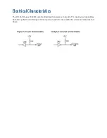
Page 16: ...tics The PIO 96 PCI uses 74LS245 octal bi directional transceivers to provide TTL input output capabilities Each bit is pulled to 5V through a 10K ohm pull up resistor to insure each bit is at a known...

Page 17: ...ns Inputs Logic High Min 2VDC Logic Low Max 0 8VDC Outputs Logic High Min 2VDC 15 mA Logic Low Max 0 5VDC 24 mA Temperature Range Operating 0 C 70 C Storage 50 C 105 C Power Consumption Supply line 5V...

Page 18: ...Example Circuits...

Page 19: ...is typically selected via an on board header block Refer to the section on Card Setup for help in choosing an I O address and IRQ 7 Make sure the Sealevel Systems adapter is securely installed in a m...

Page 20: ...ite Please refer to this to answer many common questions This section can be found at http www sealevel com faq asp 4 Sealevel Systems maintains a web page on the Internet Our home page address is htt...

Page 21: ...Appendix C Silk Screen 8009 PCB 4 20 6 80...

Page 22: ...nce at the users expense EMC Directive Statement Products bearing the CE Label fulfill the requirements of the EMC directive 89 336 EEC and of the low voltage directive 73 23 EEC issued by the Europea...

Page 23: ...e obtained by delivering the Product to Sealevel and providing proof of purchase Customer agrees to ensure the Product or assume the risk of loss or damage in transit to prepay shipping charges to Sea...

Reviews: