Capacitor - Ceramic
34
Troubleshooting
Unlike electrolytic capacitors, ceramic ca-
pacitors rarely fail in normal use. However,
if the voltage exceeds the datasheet’s rec-
ommended maximum values (breakdown
voltage), they can and will produce magic
smoke. If they look burnt, or smell burnt,
then the charge may have arced across the
dielectric layer and will have overheated
considerably.
A simple test to see if the capacitor is
functioning as it should is to measure it’s
resistance. As the capacitor charges, the
resistance will increase. Before all tests
make sure you discharge the capacitor by
bridging the leads with a screwdriver. Set
your multimeter to Ohms and attach your
multimeter probes to each lead. If the resis-
tance climbs to infinity, then the capacitor
is functioning as it should. If the resistance
reads 0 then the dielectric layer has been
compromised and the capacitor will need
replacing. This method unfortunately
doesn’t check its capacitance.
The only reliable way to test a capacitors
capacitance is to remove it from the circuit
and test it with a multimeter capable of
reading capacitance. Set your multimeter
to capacitance (Look for the
____
symbol)
and connect the multimeter to the legs of
the capacitor. If the value is no longer within
the stated tolerance, replace it.
Common Uses
Decoupling
Capacitors are often used to protect cer-
tain components from interference from
other parts of the circuit. Most common
applications are right next to any integrated
circuit (IC). The capacitor acts as a storage
reserve. If the voltage drops below the re-
quired voltage, the capacitor will use it’s
stored energy to make up the difference.
If the voltage increases above the required
voltage, the capacitor absorbs the excess
voltage. The microcontroller, or other sensi-
tive device will see a much more even volt-
age because of this. Decoupling capacitors
are placed as close to the sensitive parts
of the circuit as possible, for maximum ef-
fectiveness. To smooth higher frequencies,
you would use a low value capacitor (like a
10nF - 0.1uF ceramic capacitor). To smooth
the lower frequency noise, a higher value
would be used (often a 1-10uF electrolytic
capacitor). Decoupling capacitors feature
in most of our kits.
Filtering
Unlike resistors, who’s resistance stays
constant no mater what frequency of sig-
nal that’s passing through it, Capacitors
are reactive devices that resist higher fre-
quencies less and lower frequencies more.
Because of this, they will block DC signals
(very low frequencies) and allow AC signals
(alternating at higher frequencies) through.
This is useful when you need AC and DC
in a circuit, but only want AC signals in a
certain part. A common example of this
is a microphone circuit. The microphone
needs a DC signal to power the device,
but records AC signals (sound) from the
environment. When we pass the AC noise
through to an amplifier circuit, we want the
AC signal, but not the DC. Adding a capac-
itor in series will remove the unwanted DC
signal. (See the Sensor Array for a working
example of this)
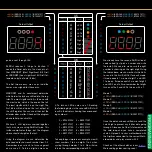
ATMega328P’s Decoupling Capacitors
AC Filter on the Sensor Array
(electrolytic Capacitor)

