Scan mode function extension for ASCII readers
3.3 Communication in scan mode
ASCII protocol for RF200
28
Operating Manual, 11/2016, C79000-G8976-C329-04
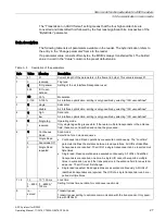
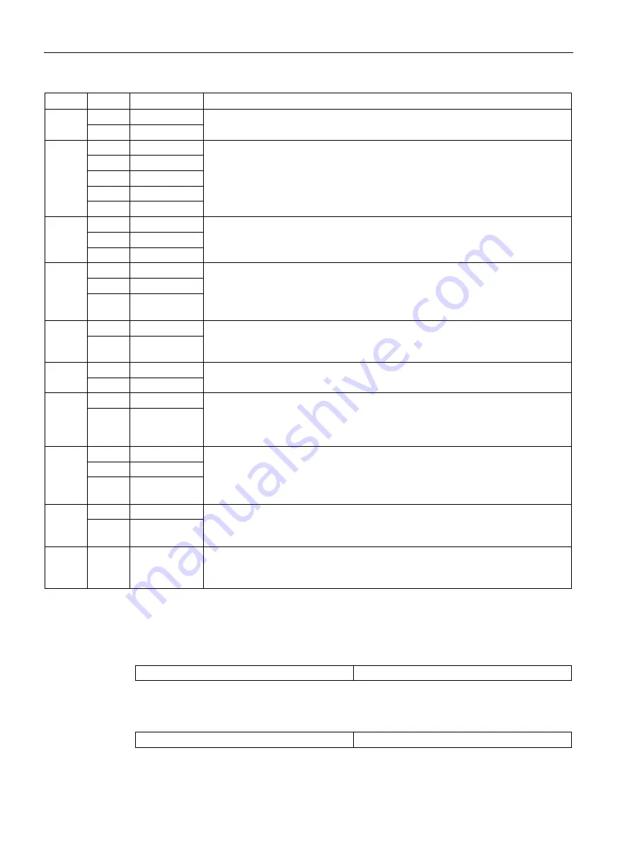
Byte
Value
Meaning
Description
10
1
RS232
Physical interface
Physical interface setting. Only possible with RF38xR.
2
reserved
11
0
9600
Baud rate
Transmission speed setting. Applies to scan mode, test mode, and frame communi-
cation.
1
19200
2
38400
3
57600
5
115200
12
0
None
Parity
Parity bit setting. Applies to scan mode, test mode, and frame communication.
1
Even
2
Odd
13
0
UID
Data record
Combination of data that the reader automatically transfers to the host in scan mode.
1
User data
2
UID + user
data
14 + 15 0
0
User data start address
Specification of address from which the user data should be read (“user data” set-
ting).
0...8192 0...8192
16 + 17 4
4
User data length
Specification of amount of user data that should be read (“user data” setting).
1...1024 1...1024
18
0
ascii
Data format
Setting for data transfer type: Bytes are transferred as binary bytes or are converted
into two ASCII characters. This parameter does not apply to the separator or end-of-
text character (binary). This parameter does not apply to frame traffic either.
1
binary
19
0
CR+LF
Separator
Setting for the separator transmitted between data when “UID + user data” is config-
ured. Not used when “UID” or “user data” is configured.
2C
‘.‘
1...FF
Any character
(not 0)
20
0
CR+LF
End-of-text character
End-of-text character transmitted at the end of a data set; separates data from differ-
ent transponders.
1...FF
Any character
(not 0)
21
1
LSB first
Byte order
LSB is transmitted first (within the block size) This parameter applies only to user
data.
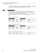
Examples of frame content for various parameter settings
Table 3- 6
“Data record” parameter, UID
UID
End-of-text character
Table 3- 7
“Data record” parameter, user data
Data
End-of-text character


