XI. Key function operation
1.
RUN/Stop mode
1
)
Under the measure mode, press and hold “R/S” key > 3 sec to enter STOP mode, SV
window will display “STOP”, main control output stops or keep the minimum output.
2
)
Under STOP mode, press and hold “R/S” key to exit STOP mode. Press “ ” key to
modify SV value.
3
)
Under STOP mode, alarm output and analog output work normally.
2. PID auto-tune operation:
1
)
Before auto-tuning, please switch off the load power, or set the meter as STOP mode.
2
)
Before auto-tuning, PV value should meet below condition: when it is PID heating
control, PV needs to be much smaller than SV; when it is PID cooling control, PV needs
to be much greater than SV.
3
)
Before auto-tuning, please set a proper alarm value or eliminate the alarm condition, in
order to prevent the auto-tuning procedure from being affected by alarm output.
4
)
Set PID type and SV value; the factory default setting is fuzzy PID.
5
)
Set as PID control, if there is OLL & OLH output limitation, please set the output to a
proper range; factory default setting is OLL=0%, OLH=100%.
6
)
Exit STOP mode, or switch on the load power, and immediately press and hold “AT ”
key to enter auto-tuning mode, then the AT indicator light is on.
7
)
The auto-tuning procedure will take some time, in order not to affect auto-tune result,
please don`t modify the parameters or power-off.
8
)
When AT light turns off, it automatically exits auto-tune mode, PID parameters will be
updated automatically, and then the meter will control automatically and precisely.
9
)
During the auto-tuning procedure, below actions will cause the termination of the
precess, press and hold “AT” key, measure beyond the scope, abnormal display, switch
to STOP mode, power-off, etc.
10
)
Note: In the occasions with output limiting operation, sometimes, even if the
auto-tuning is carried out, the best PID parameters still cannot be obtained.
11
)
Experienced users can set a proper PID parameter according to their experience.
3.PID heating and proportional cooling control operation
1
)
Set the control mode OT as 3.
2
)
PID heating control operates on OUT1; proportional cooling control operates on OUT2.
3
)
Proportional cooling control OUT2 outputs via AL1 alarm function terminals.
4
)
Please set the cooling start hystersis DB to a value greater than 5, to ensure the cooling
output will not affect the PID heating control.
5
)
Please set the cooling control cycle CP1 and the cooling proportionality coefficient PC
to the proper value.
6
)
When PV value > SV+DB value, the cooling control start to effect; the bigger value of
PV, the longer output time of OUT2
4. Auto-manual switch function
1
)
Enter common menu, set parameter A-M as “AM”.
2
)
After return back to measure control interface, press “ ” key to switch auto-manual
operation.
3
)
When it is switched to manual control, lower line LED will display output percentage:
M0~M100 (corresponding to 0%~100%), press UP key and DOWN key to modify the
output percentage.
4
)
Before the switch from manual control to auto control, in order to ensure the smooth
switch, please press Shift key to modify the SV value first.
5
)
After the meter is rebooted, the default setting is manual control and output 0%.
SET
SET
Display
LLLL/HHHH
Checking methods
Checks whether the input disconnection and whether normal of FH/ FL value,
working environment temperature and whether input signal is selected correctly.
X. Checking methods of simple fault
(
2
)
Alarm extension function table
AE1/AE2
value
0
1
2
3
4
5
Alarm handling method when
it displays HHHH/LLLL
Power on, alarm inhibition
Power on, no alarm inhibition
(
As long as the alarm condition is met, alarm
output immediately.)
Power on, alarm inhibition
(
After power on and before the PV value reaches
the SV for the first time, the alarm will not output.
After that alarm work normally)
Alarm status remains the same
Forced alarm output
Forced alarm close
Alarm status remains the same
Forced alarm output
Forced alarm close
8
7
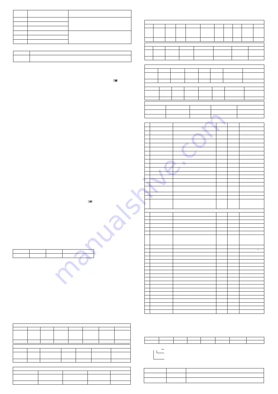
Handling of abnormal communication:
When abnormal response, put 1 on the highest bit of function code. For example: Host request
function code 0x03,and slave response function code should be 0x83.
Error code:
0x01--- Illegal function: the function code sent from host is not supported by meter
0x02--- Illegal address: the register address designated by host beyond the address range of
meter.
0x03--- Illegal data: the written data value sent from host exceeds the corresponding data range
of meter.
Communication cycle
:
Communication cycle is the time from host request to slave response data, i.e.: communication
cycle= time of request data sslave preparation time + response delay time + response
return time, e.g.: 9600 Baud rate:communication cycle of single measured data ≥250ms.
Meter adopts Modbus RTU communication protocol, RS485 half duplex communication.
Read function code 0x03, write function code 0x10 or 0x06. Adopt 16 digit CRC check, the
meter does not return for error check. Factory default setting: slave address 1, baud rate 9600,
no check, 8 digits data bit, 1 digit stop bit, data type is 16 digits signed (unsigned) int.
Data frame format:
1. Read register
For example:Host reads integer SV(set value 200
)
The address code of SV is 0x2000, because SV is integer(2 dyte), seizes 1 data register. The
memory code of decimal integer 200 is 0x00C8. Note: when reading data, should read DP
value or confirm DP menu value first to ensure the decimal point postion, after that transform
the read data to get the actual value. Conversely, it should transform the data to
corresponding ratio before writing the data in meter
XII. Communication protocol
Start bit
Data bit
1
8
1
Set in Menu PRTY
Stop bit
Check bit
XIII. Version and Revision History
2021.06.30
1st edition
A/0 version
Date
Version
Revision content
Meter
ADD
Function
code
Start
ADD
high bit
Start
ADD
low bit
Data byte
length
high bit
Data byte
length
low bit
※
CRC
code
low bit
※
CRC
code
high bit
Host request (Read multi-register)
1 2 3 4 5 6 7 8
0x01 0x03 0x20 0x00 0x00 0x01 0x8F 0xCA
Function code abnormal answer: (For example: host request ADD is 0x2011)
1
2
3
8
9
0x01 0x83 0x02 0xC0 0xF1
Meter ADD Function code
Error code
Slave abnormal answer(Read multi-register)
※
CRC code
low bit
※
CRC code
high bit
Slave normal answer(Read multi-register)
Data
low bit
Data
high bit
※
CRC code
low bit
※
CRC code
high bit
1
2
3
4
5
6
7
0x01
0x03
0x02
0x00
0xC8
0xB9
0xD2
Meter
ADD
Function
code
Data byte
length
2. Write multi-register
For example: Host use 0x10 function code write SV
(
set value 150
)
ADD code of SV is 0x2000, because SV is integer(2 dyte), seizes 1 data register. The hexadecimal
code of decimal integer 150 is 0x0096.
0x01 0x10 0x20 0x00 0x00 0x01 0x02 0x00 0x96
Meter
ADD
Function
code
Start ADD
high bit
Start ADD
low bit
Data byte
length high bit
Data byte
length low bit
※
CRC code
low bit
※
CRC code
high bit
Slave normal answer (write multi-register)
8
7
6
5
4
3
2
1
0x09
0x0A
0x01
0x00
0x00
0x20
0x10
0x01
Data
low bit
※
CRC code
low bit
※
CRC code
high bit
ADD
low bit
Data
high bit
Meter
ADD
Function
code
ADD
high bit
Data
low bit
※
CRC code
low bit
※
CRC code
high bit
ADD
low bit
Data
high bit
Meter
ADD
Function
code
ADD
high bit
Host write SV with 0x06 function
(
set value 150
)
Slave normal answer
(
write single-register
)
8
7
6
5
4
3
2
1
0x00
0x00
0x20
0x06
0x01
Host request
(
write single-register
)
8
7
6
5
4
3
2
1
0x64
0x02
0x96
0x64
0x02
0x96
0x00
0x00
0x20
0x06
0x01
Meter ADD Function code
Error code
※
CRC code low bit
※
CRC code high bit
5
4
3
2
1
0xA1
0x01
0x86
0x02
0xC3
Slave abnormal answer ( write single-register)
Meter
ADD
Function
code
Start
ADD
high bit
Start
ADD
low bit
Data byte
length
high bit
Data
high
bit
Data
low
bit
Data byte
length
low bit
Data
byte
length
1 2 3 4 5 6 7 8 9 10 11
Host request (write multi-register)
0x07
0xFC
※
CRC
code
low bit
※
CRC
code
high bit
Default 1 decimal point
Meter parameters address mapping table
0x2000(48193)
0x2001(48194)
1
2
No. Add(Register No
①
)
Register R/W
Remark
1
1
R/W
R/W
0x2003
(48196)
4
1
R/W
0x2002
(48195)
3
1
R/W
24
25
Output mode ACT
R/W
26
RUN/STOP operation
R/W
1st alarm extended function AE1
R/W
22
23
Control mode OT
2nd alarm extended function AE2
R/W
R/W
20
21
1st alarm mode AD1
Reserve
2nd alarm mode AD2
R/W
R/W
1:RUN 2:STP
3:Run auto-tune
4:Stop auto-tune
0x2004
(48197)
0x2005
(48198)
0x2006
(48199)
0x2007
(48200)
0x2008
(48201)
0x2009
(48202)
0x200A
(48203)
5
6
7
8
9
10
11
Default 1 decimal point
Engineering work
without decimal point
1
1
1
1
1
1
1
1
1
1
1
1
1
1
R/W
R/W
R/W
R/W
R/W
R/W
R/W
R/W
R/W
R/W
0x200B
(48204)
0x200C
(48205)
0x200D
(48206)
0x200E
(48207)
0x200F
(48208)
0x2010
(48209)
12
13
14
15
16
17
1
1
1
R/W
R/W
R
0~100
0x2011
(48210)
18
1
1
1
1
0:Auto; 1: Manual
2:Auto-Manual
switch
0x2012
(48211)
19
Set value SV
1st alarm value AL1
Variable name
2nd alarm value AL2
1st alarm hysteresis HY1
2nd alarm hysteresis HY2
Display low limit FL
Display high limit FH
Analog output low limit BRL
Analog output high limit BRH
Control output low limit OLL
Control output high limit OLH
Heat & Cool control dead zone DB
Overshoot limit OVS
Proportional coefficient of cooling PC
Amend value PS
PV fuzzy tracking value DTR
Measured value PV
Output percentage MV
Auto-Manual switch A-M
1
R/W
R
0x2105
(48454)
0x2106
(48455)
0x2102
(48451)
0x2103
(48452)
0x2104
(48453)
0x2101
(48450)
0x2100
(48449)
R/W
R/W
R/W
R/W
R/W
R/W
R/W
R/W
R/W
R/W
R/W
R/W
1
1
1
1
1
1
1
1
1
1
1
1
1
1
1
1
1
1
27
28
29
30
31
32
33
34
35
36
37
Decimal pointDP
Unit display UT
Filter constants FT
Proportional coefficient P
Integral time I
Differential time D
Control speed fine-tune SPD
Heating control cycle CP
Cooling control cycle CP1
Cooling delay time PT
Optional input signal INP
25(℃)26( F)
No decimal point
No decimal point
No decimal point
No decimal point
No decimal point
No decimal point
Refer to signal table
41
42
43
44
PID arithmetic type PDC
Lock LCK
Meter name
Output state
38
39
40
Meter address ADD
Communication baud rate BAD
Comm. data transfer sequence
DTC
R
R
R
R
R
R
Note
②
Note ③
0x2107
(48456)
0x2108
(48457)
0x2109
(48458)
0x210A
(48459)
0x210B
(48460)
0x210C
(48461)
0x210D
(48462)
0x210E
(48463)
0x210F
(48464)
0x2110
(48465)
0x2111
(48466)
0x2115
(48470)
0x2116
(48471)
0x2117
(48472)
0x2118
(48473)
0x2112
(48467)
0x2113
(48468)
0x2114
(48469)
0x2119
(48474)
45
Parity Check PRTY
1
R
R
:
Read only
;
R/W
:
Read & write
D7 D6 D5 D4 D3 D2 D1 D0
AT AL2 AL1 OUT2 OUT1
STOP
HHHH
LLLL
Note
①
: The register number is the address converted to decimal plus 1 and then the register
identification code 4 is added in front; for example: the register number of the data address
0x2000 is 8192 + 1 = 8193 and then 4 is added in front, that is, the register number 48193;
Related applications can be seen, such as Siemens S7-200 PLC.
Note
②
: Measurement status indication. When the data bit is 1, it means execution, and when it
is 0, it means no execution.
Note
③
: DTC communication data transmission sequence description
Reserve
Byte transfer order: when it is 0, the sequence is 1, 2; and when it is 1, the
sequence is 2, 1
Reserve
□ □ □
DTC:


